
Compound fertilizer production equipment
A technology for production equipment and compound fertilizers, applied to mixers, mixers with rotating stirring devices, dissolution, etc., can solve the problems of complex production equipment and high cost, and achieve simple structure, avoid jamming, and large loosening area Effect
Patent Information
- Authority / Receiving Office
- CN · China
- Patent Type
- Applications(China)
- Current Assignee / Owner
- Publication Date
- 2019-02-12
Smart Images
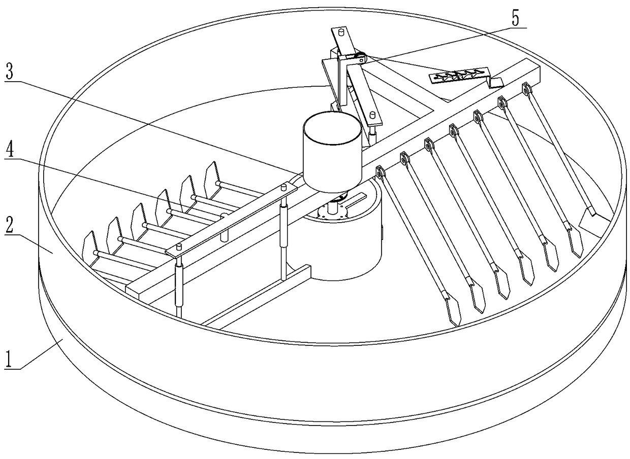
Figure 1 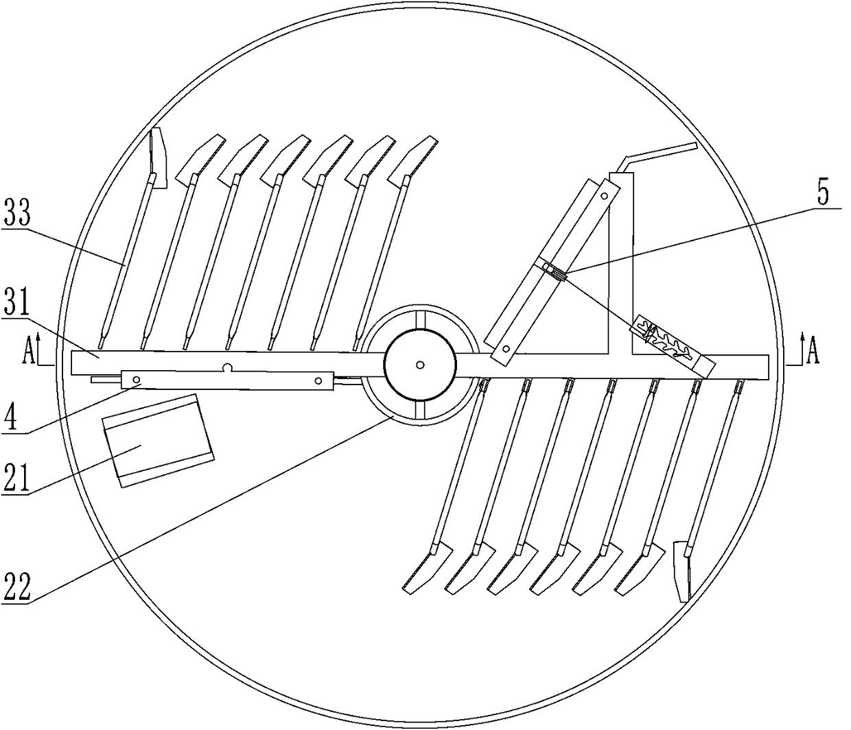
Figure 2 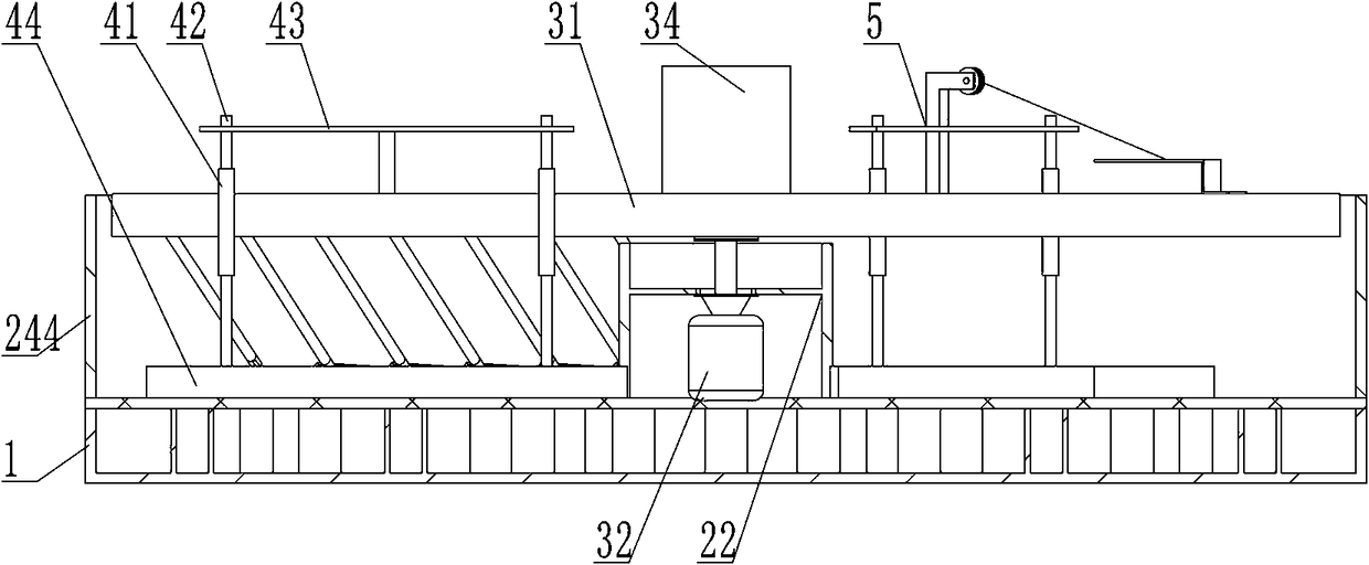
Figure 3
Abstract
Description
technical field
[0001] The invention belongs to the technical field of compound fertilizer production and relates to compound fertilizer production equipment. Background technique
[0002] Compound fertilizer production often uses soil testing formulas to measure soil nutrients. Soil testing formula fertilization is based on soil tests and fertilizer field experiments. According to the law of crop fertilizer requirements, soil fertilizer supply performance and fertilizer effects, organic fertilizers are used rationally. On the basis of this, the application amount, fertilization period and application method of nitrogen, phosphorus, potassium, and medium and trace elements are proposed. There are many compound fertilizer production processes, such as drum granulation, disc granulation, spray granulation and tower granulation. The existing problems are:
[0003] The production equipment is too complicated and the cost is high;
[0004] The surface particles of the product a...
Examples
Embodiment Construction
[0041] Such as Figure 1~Figure 12 Among them, a kind of compound fertilizer production equipment, it comprises heating device 1, feeding basin 2, material mixing device 3, material loosening mechanism 4 and scraping material mechanism 5; Located in the material basin 2 and connected thereto, the material loosening mechanism 4 and the material scraping mechanism 5 are located at both ends of the material mixing device 3 and connected; the material mixing device 3 drips and rotates the material. The structure is simple, by setting the material basin 2 on the upper side of the heating device 1 in contact with it, and setting the mixing device 3 in the material basin 2, and connecting the loosening mechanism 4 and the scraping mechanism 5 with both ends of the mixing device 3, and driven by the motor 32 The rotation of the cantilever 31 drives the rake teeth 33 to rotate and loosen the material body. The loosening mechanism 4 and the scraping mechanism 5 rotate the loosening and ...