Numerical control pipe bending machine of improved structure

A technology of structure improvement and pipe bending machine, which is applied in the field of pipe processing equipment, can solve problems such as interference, interference during bending pipe forming process, unfavorable bending and forming pipe bending structure, etc., and achieve the effects of reducing interference, optimizing layout and improving precision

Pending Publication Date: 2019-03-01
浙江和良智能装备有限公司
View PDF12 Cites 3 Cited by
  • Summary
  • Abstract
  • Description
  • Claims
  • Application Information

AI Technical Summary

Problems solved by technology

[0003] In the process of pipe bending, in order to prevent the unexpected slippage between the pipe blank and the round die and the clamping die during the pipe bending process, the clamping force between the clamping die and the round die is required to reach a certain strength, and oil cylinders or air cylinders are often used together with boosters. The force mechanism cooperates, as the clamping mold assembly disclosed in the patent literature with the notification number CN207119660U, the clamping mold drive mechanism of its clamping mechanism includes a booster rocker, a booster connecting rod, a lever and a cylinder or oil cylinder, as shown in the accompanying drawings It shows that the cylinder swings during the clamping process, and the axial dimension of the bending pipe spindle is relatively large, which is easy to interfere with the bending pipe forming process, which is not conducive to forming a special shape of the bending pipe structure
[0004] In addition, since the pipe bending motor is usually installed under the round die and the distance in the lateral direction is relatively small, such as the numerically controlled pipe bending machine disclosed in the patent document CN107626785A, as its attached Figure 5 As shown, the position arrangement of the bending motor 32 is also likely to interfere with the bending process of the tube blank

Method used


Image

  • Numerical control pipe bending machine of improved structure
  • Numerical control pipe bending machine of improved structure
  • Numerical control pipe bending machine of improved structure

Examples


Embodiment 1

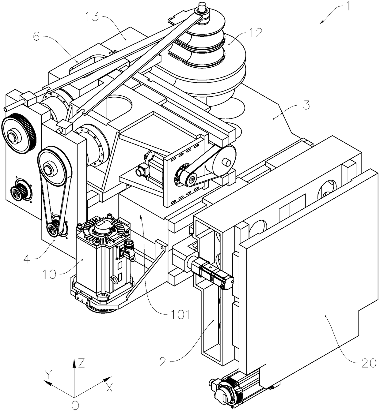
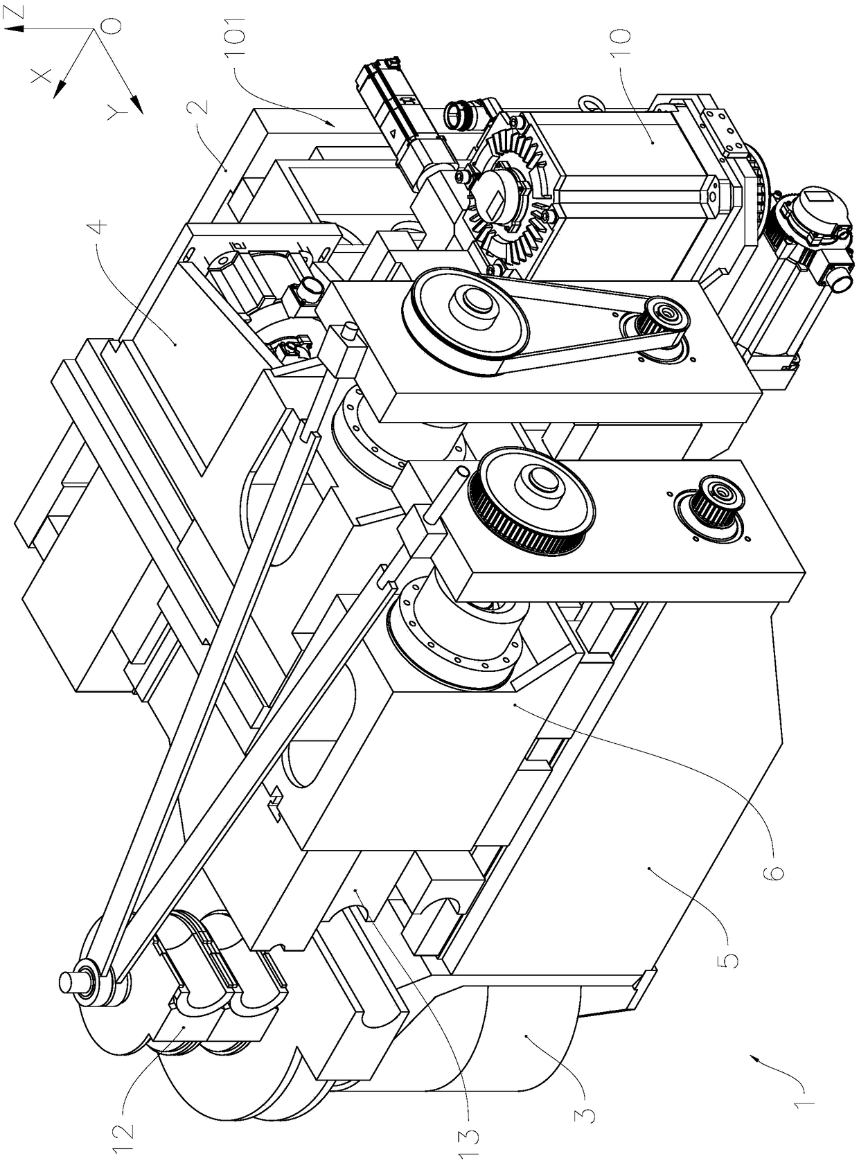
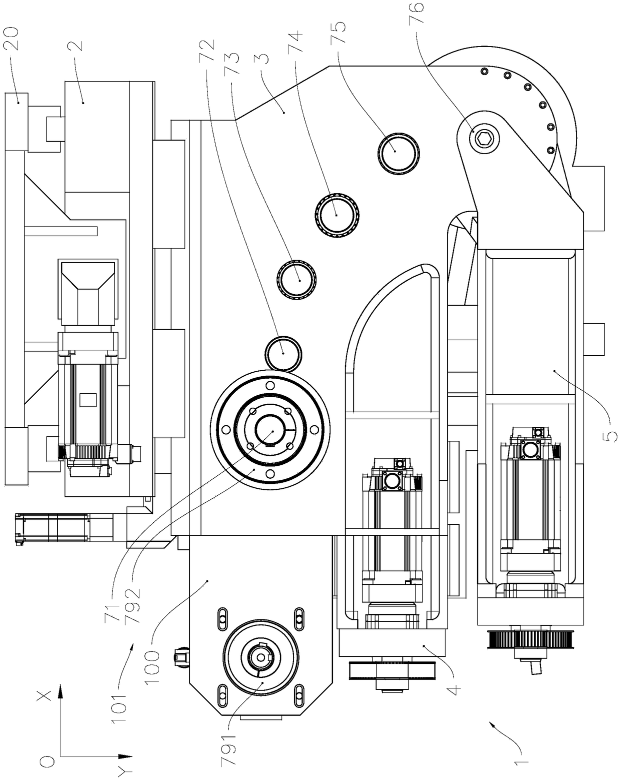
[0038] see Figure 1 to Figure 14 , The CNC pipe bending machine includes a frame, a control unit, a machine head 1 and a feeding trolley installed on the frame and controlled by the control unit. The machine head includes a mold changing unit 2, a machine head base 3, a mold guide unit 4 installed on the machine head base 3, a pipe bending motor 10, a pipe bending main shaft and a pipe bending torque transmission mechanism, which are coaxially installed on the pipe bending main shaft The circular mold 12 and the swing arm 5 on the top, and the clamping mold 13 and the clamping mold drive mechanism 6 installed on the swing arm 5. The pipe bending torque transmission mechanism is used to transmit the torque output by the pipe bending motor 10 to the pipe bending main shaft, so as to drive the clamping die 13 and the round die 12 to rotate synchronously, so as to form the pipe blank into a corresponding curved pipe structure.

[0039] In this embodiment, the control unit includ...

Embodiment 2

[0067] As an illustration of Embodiment 2 of the present invention, only the differences from Embodiment 1 above will be described below.

[0068] see Figure 15 to Figure 17, in this embodiment, a ball screw mechanism is used instead of the above-mentioned planetary roller screw mechanism to construct the clamping drive mechanism 6 . Correspondingly, the reduction transmission mechanism adopts a gear train reduction box 64 , and the support seat is a reduction box body 640 fixed on the swing end of the swing arm 5 .

[0069] Clamping base 63 comprises the bottom plate 631 that is connected with the slide block on the rolling guide rail 630, is fixed on the box-type seat portion 632 on one end portion of the base plate 631 adjacent to the elbow main shaft, and is fixed on the box-type seat portion 632 away from the bend. One side of the pipe main shaft and the triangular reinforcing rib 633 between the other end of the bottom plate 631; the clamping mold 13 is detachably fixe...


PUM


Abstract

The invention relates to a numerical control pipe bending machine of an improved structure, and belongs to the technical field of pipe processing and treating. A machine head for numerical control pipe bending comprises a die guiding unit, a pipe bending motor, a swing arm, a clamping die and a clamping die driving mechanism, and the clamping die and the clamping die driving mechanism are mountedon the swing arm; the clamping die driving mechanism comprises a clamping die servo motor fixedly arranged in an arm body cavity of the swing arm, a lead screw mechanism located above the arm body, aclamping die base fixedly arranged on a lead screw nut and a speed reduction transmission mechanism arranged on the side of the swing end of the swing arm; in the transverse direction perpendicular tothe axial direction of a feeding main shaft, the pipe bending motor is fixedly arranged on the end side of a machine head base in a manner of leaving from a pipe bending main shaft; in the axial direction, the pipe bending motor is located on the side, adjacent to a feeding trolley, of the pipe bending main shaft; and an auxiliary pushing mechanism of the die guiding unit and a clamping mechanismdefine an angle-shaped avoiding channel located over the pipe bending motor. Based on optimization of the structure and position layout of all functional units on the machine head, interference in the pipe bending process can be effectively reduced, and the numerical control pipe bending machine can be widely used in the fields of air conditioning, aviation and the like.

Description

technical field [0001] The invention relates to pipe material processing equipment, in particular to a numerically controlled pipe bending machine with improved structure. Background technique [0002] CNC pipe bending machines are widely used in air conditioners, automobiles, ships, aerospace and other industrial fields, mainly including frame, control unit, feeding trolley and machine head installed on the frame and controlled by the control unit; The mold guide unit, pipe bending motor, pipe bending main shaft and pipe bending torque transmission mechanism installed on the headstock, the round die and swing arm coaxially installed on the pipe bending main shaft, and the Clamping die and clamping die driving mechanism; the circular die is used to control the radius of the pipe bend, and is installed on the swing arm. Driven by the clamping die driving mechanism, the clamping die clamps the pipe together with the circular die, and driven by the pipe bending spindle, And sy...

Claims


Application Information

Patent Timeline
Patent Type & Authority Applications(China)
IPC IPC(8): B21D7/12B21D7/025B21D7/16
CPCB21D7/025B21D7/12B21D7/16
Inventor 赵俊强蔡前龙张良张明涛
Owner 浙江和良智能装备有限公司
Why Eureka
Try Eureka