Solar fallen leaf collecting and treating device

A technology of processing device and collecting device, which is applied in grain processing, road cleaning, construction, etc., can solve the problems of overworked cleaning workers, increased workload of cleaning workers, and inability to reduce workload, etc., so as to facilitate the collection of fallen leaves and accelerate the decomposition of fallen leaves. Effect

Active Publication Date: 2019-03-22
诸暨市沃特袜业有限公司
View PDF8 Cites 3 Cited by
  • Summary
  • Abstract
  • Description
  • Claims
  • Application Information

AI Technical Summary

Problems solved by technology

[0002] In autumn, a large number of leaves fall on the road, which increases the workload of the cleaners. Although the cleaning tools used by the cleaners can collect falle

Method used


Image

  • Solar fallen leaf collecting and treating device
  • Solar fallen leaf collecting and treating device
  • Solar fallen leaf collecting and treating device

Examples


specific Embodiment approach 1

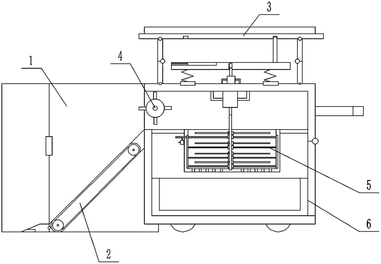
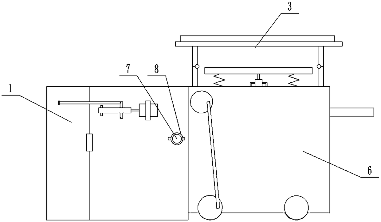
[0034] Combine below figure 1 , 2 , 3, 4, 5, 6, 7, 8, 9, 10, 11, 12, 13, 14 illustrate this embodiment, the present invention relates to a fallen leaf processing device, more specifically a solar fallen leaf collection and processing device , including gathering device 1, collecting device 2, solar support 3, pushing device 4, crushing device 5, housing 6, motor I7, motor bracket I8, not only convenient for collecting fallen leaves, but also can crush fallen leaves, and accelerate the decomposition of fallen leaves during centralized processing .

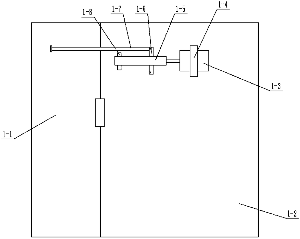
[0035]The gathering device 1 is composed of a movable plate 1-1, a fixed plate 1-2, a motor II 1-3, a motor support II 1-4, a screw 1-5, a rotating disk 1-6, a connecting rod 1-7, a bracket 1-8, An annular groove I1-9 is formed; one end of the movable plate 1-1 is flexibly connected to the fixed plate 1-2 through a hinge; the motor bracket II1-4 is connected with a motor II1-3 through bolts, and the motor bracket II1- 4 is fixedl...

specific Embodiment approach 2

[0044] Combine below figure 1 , 2 . hemispherical.

specific Embodiment approach 3

[0045] Combine below figure 1 , 2 . 7 are provided with three, and the angle between the slot 3-13 in the middle and the adjacent slots 3-13 on both sides is 90°.

[0046]The working principle of the present invention is: when using the device, push the pusher 6-8 to drive the device to move forward. -6 is threadedly connected with the screw rod 1-5, so the turntable 1-6 moves left and right on the screw rod 1-5, the turntable 1-6 drives the connecting rod 1-7 to move, and the connecting rod 1-7 drives the movable plate 1-1 around it The hinge at the upper end rotates to gather the surrounding trees to the vicinity of the collection device 2; push the push handle 6-8, and when the movable block 2-4 moves to the vicinity of the fallen leaves, the slope on the movable block 2-4 collects the fallen leaves to the movable block 2- 4, and then collected into the housing 6 by the conveyor belt 2-2, when encountering a pothole or a raised place, the movable block 2-4 can move up an...


PUM


Abstract

The invention relates to a fallen leaf treating device, and particularly relates to a solar fallen leaf collecting and treating device. The device has the advantages that fallen leaves are conveniently collected, the fallen leaves can be pulverized, and the decomposing of the fallen leaves is accelerated in concentrating treatment. The device is characterized in that the lower end of a supportingrod II is movably connected with the upper end of a housing body through a hinge; a sliding block is arranged at the lower end of a spring, and the sliding block is in clearance fit with an annular groove IV; a tube is rotatably connected with the interior of the housing body, and the tube is located in a feeding port; a fixing plate is fixedly connected with the outer side of the housing body through a bolt; a fixing housing is connected with the outer side of the housing body, and the fixing housing is located at the lower end of the feeding port; a motor I is fixedly connected with a motorsupporting frame I and is connected with a cylinder; the motor supporting frame I is fixedly connected with the outer end of the fixing plate; a motor supporting frame IV is fixedly connected with theinner top of the housing body; a pulverizing tube is fixedly connected with the interior of a circular hole.

Description

technical field [0001] The invention relates to a device for treating fallen leaves, in particular to a device for collecting and treating fallen leaves with solar energy. Background technique [0002] In autumn, a large number of leaves fall onto the road, resulting in an increase in the workload of the cleaners. Although the cleaning tools used by the cleaners can collect fallen leaves, they cannot reduce the workload and cause the cleaners to be very tired. Therefore, this design is designed The utility model relates to a device for collecting and treating fallen leaves by solar energy. Contents of the invention [0003] The invention provides a device for collecting and treating fallen leaves by solar energy, which not only facilitates collecting fallen leaves, but also crushes fallen leaves, and accelerates the decomposition of fallen leaves during centralized processing. [0004] In order to solve the above technical problems, the present invention relates to a fall...

Claims


Application Information

Patent Timeline
IPC IPC(8): E01H1/04B02C18/06B02C18/10B02C18/24
CPCB02C18/067B02C18/10B02C18/24E01H1/042
Inventor 苏春娇
Owner 诸暨市沃特袜业有限公司
Why Eureka
Try Eureka