Eureka AIR delivers breakthrough ideas for toughest innovation challenges, trusted by R&D personnel around the world.

Table clock movement fixed frame

A technology of fixing frame and movement, applied in workpiece clamping devices, manufacturing tools, etc., can solve the problems of narrow application surface, inconvenient fixing and inconvenience of the main plate

Pending Publication Date: 2019-03-29
TIANJIN HANKE TECH
View PDF0 Cites 0 Cited by
  • Summary
  • Abstract
  • Description
  • Claims
  • Application Information

AI Technical Summary

Problems solved by technology

[0002] The table clock movement usually includes a circular or rectangular lower splint (main splint) and at least one upper splint, with multiple gears interposed between the splints to control the travel time of different hands, so the movement of the table clock is usually larger , the structure inside the movement is also relatively complicated. During the process of installing the movement, the axles of some gears need to pass through the splint of the movement to facilitate the installation of the pointer or the timekeeping mechanism of the clock, so that the main splint usually needs to be suspended in the middle of the movement during the installation process. On the desktop, this will cause the main splint to be inconvenient to fix and vibrate, and it is not convenient for the shaft tips of each axle to be inserted into the preset openings of the upper splint, resulting in inconvenient assembly of the movement;
[0003] At present, table clock movements are usually erected on the table using a frame structure, so that the main splint can be separated from the table. However, the existing frame is usually a fixed structure, which is only suitable for the movement of a specified size, and the applicable surface is narrow, and the frame The structural part is convenient to adjust the gear shaft passing through the main splint from the bottom of the main splint, but it is not convenient for the gear shaft to cooperate with the upper splint, making the assembly efficiency low

Method used


Image

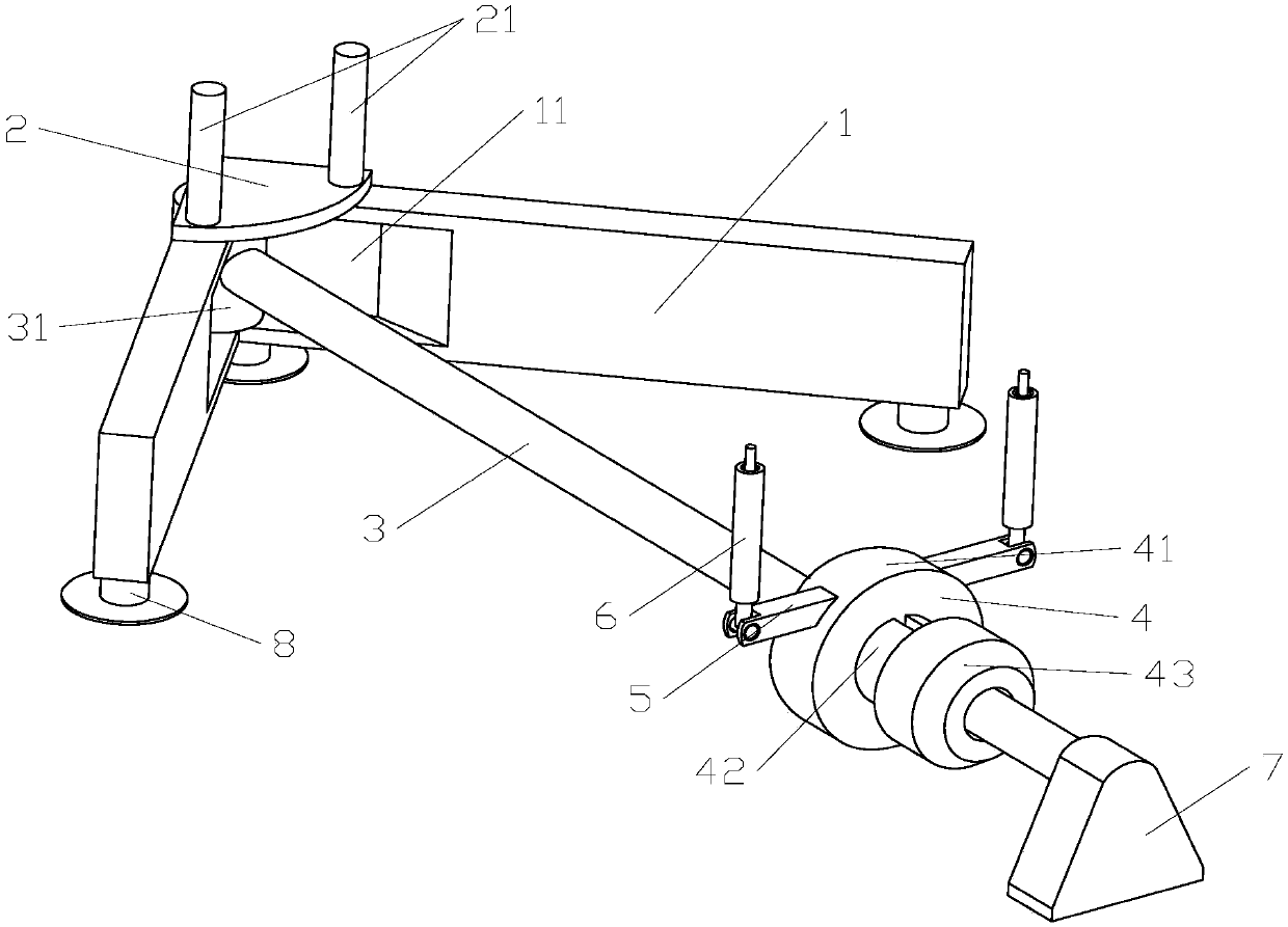
  • Table clock movement fixed frame
  • Table clock movement fixed frame
  • Table clock movement fixed frame

Examples


Embodiment Construction

[0028] It should be noted that, in the case of no conflict, the embodiments of the present invention and the features in the embodiments can be combined with each other.

[0029] In describing the present invention, it should be understood that the terms "center", "longitudinal", "transverse", "upper", "lower", "front", "rear", "left", "right", " The orientations or positional relationships indicated by "vertical", "horizontal", "top", "bottom", "inner" and "outer" are based on the orientations or positional relationships shown in the drawings, and are only for the convenience of describing the present invention and Simplified descriptions, rather than indicating or implying that the device or element referred to must have a particular orientation, be constructed and operate in a particular orientation, and thus should not be construed as limiting the invention. In addition, the terms "first", "second", etc. are used for descriptive purposes only, and should not be understood ...


PUM


Abstract

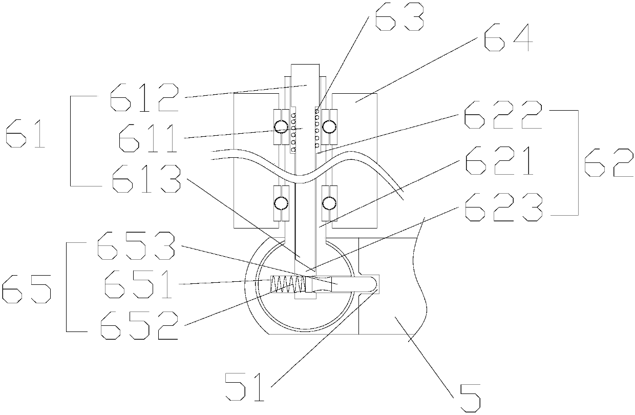
The invention provides a table clock movement fixed frame. The fixed frame comprises two crossed supporting frames, the upper surfaces of the supporting frames vertically and upwards extend to be provided with at least two fixed clamping rods, the supporting frames are crossed to be hinged to a guide rod, and the guide rod is vertically provided with a movable clamping rod capable of moving towards the fixed clamping rods. According to the table clock movement fixed frame, through fit between the fixed clamping rods and the movable clamping rod, the guide rod is used for enabling the size of space between the clamping rods to be adjustable.

Description

technical field [0001] The invention belongs to the field of fixtures and tooling, in particular to a fixing frame for a table clock movement. Background technique [0002] The table clock movement usually includes a circular or rectangular lower splint (main splint) and at least one upper splint, with multiple gears interposed between the splints to control the travel time of different hands, so the movement of the table clock is usually larger , the structure inside the movement is also relatively complicated. During the process of installing the movement, the axles of some gears need to pass through the splint of the movement to facilitate the installation of the pointer or the timekeeping mechanism of the clock, so that the main splint usually needs to be suspended in the middle of the movement during the installation process. On the desktop, this will cause the main splint to be inconvenient to fix and vibrate, and it is not convenient for the shaft tips of each axle to...

Claims


Application Information

Patent Timeline
Patent Type & Authority Applications(China)
IPC IPC(8): B25B11/02
CPCB25B11/02
Inventor 徐凯
Owner TIANJIN HANKE TECH
Why Eureka
Eureka Blog
Learn More