LED wall lamp

A technology of LED wall lamp and LED lamp, which is applied in the direction of lighting devices, light sources, fixed lighting devices, etc., can solve the problems of not being able to meet the requirements of different angles of illumination, difficulty in changing the illumination angle of wall lamps, and invariable illumination angles, etc., achieving simple structure and convenient Adjustment, practical effect

Inactive Publication Date: 2019-03-29
江苏泓睿德智能科技有限公司
View PDF6 Cites 2 Cited by
  • Summary
  • Abstract
  • Description
  • Claims
  • Application Information

AI Technical Summary

Problems solved by technology

[0002] The wall lamp is an auxiliary lighting decorative lamp installed on the indoor wall. After the existing wall lamp is installed, the irradiation angle cannot be changed. If you need to illuminate other angles, you need to use other light sources, especially in buildings with high floors. , It is more difficult to change the irradiation angle of high wall lamps, which cannot meet the irradiation requirements of different angles

Method used


Image

  • LED wall lamp
  • LED wall lamp

Examples


specific Embodiment approach 1

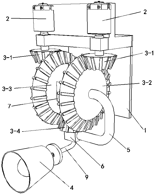
[0009] Specific implementation mode one: as Figure 1~Figure 2 As shown, the present invention discloses an LED wall lamp, which includes an LED lamp body 4, a bottom plate 1, a fourth bevel gear 3-4, a connecting rod 5, a connecting seat 6, a connecting block 7, an L-shaped rod 9, and two motors 2 , two first bevel gears 3-1, two second bevel gears 3-2 and two third bevel gears 3-3, the base plate 1 is fixed on the wall, and one end of the base plate 1 is connected to two left and right vertical The motors 2 arranged side by side are fixedly connected, and the two motors 2 are powered by the same power supply at the same time, and are controlled by the same remote controller 8. The output shafts of the two motors 2 are respectively connected to a first bevel gear 3-1 arranged horizontally. The middle part of each said first bevel gear 3-1 is meshed with the corresponding vertically arranged second bevel gear 3-2, and the non-gear end of each said second bevel gear 3-2 is It ...

specific Embodiment approach 2

[0010] Specific implementation mode two: as figure 1 As shown, this embodiment is a further description of Embodiment 1. The two motors 2 are both micro motors, and both of the micro motors are geared motors.

specific Embodiment approach 3

[0011] Specific implementation mode three: as figure 1 As shown, this embodiment is a further description of specific embodiment 1. The middle part of the connecting seat 6 is provided with a through hole in the up and down direction, and a shaft is rotated in the through hole. One end of the shaft is connected to the The middle part of the non-gear end of the fourth bevel gear 3-4 is fixedly connected, and the other end of the shaft is fixedly connected with the installation end of the LED lamp body 4

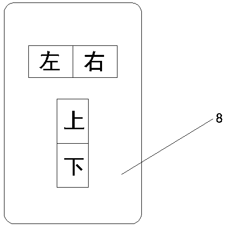
[0012] When using the present invention, the opening and closing of the two motors 2 and the direction of rotation of the two motors 2 are controlled by the "up", "down", "left" and "right" buttons on the remote controller 8 (by the remote controller 8 The technology of controlling the motor 2 is the same as that of the current remote control fan or ceiling lamp, which is the prior art), the "up" and "down" buttons on the remote control 8 control the two motors 2 to move in re...


PUM


Abstract

The invention relates to an LED wall lamp. One end of a bottom plate is fixedly connected with two motors which are arranged vertically left and right in a parallel mode. Output shafts of the two motors are fixedly connected with the middles of horizontally arranged first bevel gears correspondingly. Each first bevel gear is in meshing connection with a corresponding vertically arranged second bevel gear. The non-gear end of each second bevel gear is fixedly connected with the non-gear end of a corresponding vertically arranged third bevel gear. The middles of the two third bevel gears are rotationally connected with the two ends of a connecting block. The two third bevel gears are in meshing connection with the same fourth bevel gear. The middle of the fourth bevel gear is fixedly connected with one end of an L-shaped rod through a shaft rod. The other end of the L-shaped rod is fixedly connected with the installing end of an LED lamp body. The shaft rod is rotationally connected witha connecting seat. The connecting seat is fixedly connected with one second bevel gear through a connecting rod. According to the LED wall lamp, the illuminating angle of the LED lamp body can be adjusted conveniently, the structure is simple, use is convenient, and practicability is high.

Description

technical field [0001] The invention relates to an LED lamp, in particular to an LED wall lamp. Background technique [0002] The wall lamp is an auxiliary lighting decorative lamp installed on the indoor wall. After the existing wall lamp is installed, the irradiation angle cannot be changed. If you need to illuminate other angles, you need to use other light sources, especially in buildings with high floors. Therefore, it is more difficult to change the illumination angle of high wall lamps, which cannot meet the illumination requirements of different angles. Contents of the invention [0003] In order to solve the deficiencies presented in the background art, the present invention provides an LED wall lamp. [0004] To achieve the above purpose, the present invention adopts the following technical solutions: an LED wall lamp, including an LED lamp body, a bottom plate, a fourth bevel gear, a connecting rod, a connecting seat, a connecting block, an L-shaped rod, two mo...

Claims


Application Information

Patent Timeline
IPC IPC(8): F21S8/00F21V21/04F21V21/14F21Y115/10
CPCF21S8/036F21V21/047F21V21/14F21Y2115/10
Inventor 戴冰李蕊付春明
Owner 江苏泓睿德智能科技有限公司
Why Eureka
Try Eureka