
Tire structure

A tire and steel structure technology, applied in tire parts, non-pneumatic tires, transportation and packaging, etc., can solve problems such as non-slip, stab-proof, high temperature, etc.

Pending Publication Date: 2019-04-16
ZHEJIANG LIFUDE MACHINERY
View PDF0 Cites 0 Cited by
  • Summary
  • Abstract
  • Description
  • Claims
  • Application Information

AI Technical Summary

Problems solved by technology

[0002] The car tires in the prior art are all made of rubber materials, which cannot be well adapted to special road conditions such as anti-skid, anti-stab, high temperature, etc.

Method used

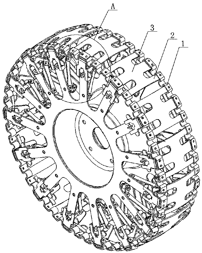
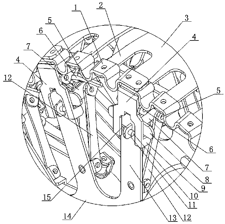

Image

  • Tire structure
  • Tire structure
  • Tire structure

Examples


Embodiment Construction

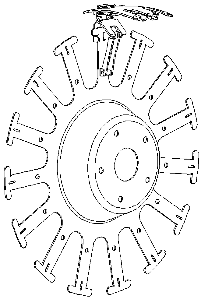
[0021] As shown in the figure, the tire structure of the present invention is composed of fifteen steel structure units arranged around the circumference to form a rolling body that can bear a certain weight. Each steel structure unit includes a cover plate 3, a limit plate 4, a pulley Plate 7, upper hinge plate 6 and lower hinge plate 12, cover plate 3, limit plate 4, pull plate 7, upper hinge plate 6 and lower hinge plate 12 are spring steel stamping parts, and the cover plates of adjacent steel structure units 3 are fixedly connected by elastic bending plates 1, and the two sides of each cover plate 3 are extended outward with three elastic slats 2, and the adjacent elastic slats 2 are connected by elastic bending plates 1, and the elastic bending plates 1 is a spring steel stamping with U-shaped bending. The limiting plate 4 is fixed on both sides of the cover plate 3, and the limiting plate 4 can be radially moved on the central disk 14. The outer circle of the central di...


PUM


Abstract

The invention discloses a tire structure. A rolling body capable of bearing a certain weight is formed by combining a plurality of circumferentially-arranged steel structure units; the tire structureis characterized in that each steel structure unit comprises a cover plate, limiting plates, a pulling plate and upper and lower hinge plates, the cover plates of every adjacent steel structure unitsare connected by an elastic bending plate, every two limiting plates are fixed at the two sides of the corresponding cover plate, the limiting plates can be radially and movably arranged in a centraldisc, and the upper and lower hinge plates are hinged to each other through hinge shafts located at the inner side of the central disc; a free end of each upper hinge plate is hinged to the corresponding limiting plate, a free end of each lower hinge plate is hinged to the central disc, the inner side end of each pulling plate pulls a triangular hinge body formed by the corresponding upper and lower hinge plates, and the outer side ends of the pulling plates pull the central disc. The invention provides a steel tire. The steel tire has the most reasonable stress structure and can be applied tospecial road conditions such as skidding resistance, stabbing resistance and high temperature.

Description

technical field [0001] The invention relates to an improved invention of a car tire structure. Background technique [0002] The automobile tires of the prior art are all made of rubber materials, which cannot be well adapted to special road conditions such as anti-skid, anti-stab, high temperature and the like. Contents of the invention [0003] In view of the deficiencies in the prior art, the purpose of the present invention is to provide a tire structure with a reasonable force-bearing structure, which can be applied to special road conditions such as anti-slip, anti-puncture, high temperature and the like. [0004] The present invention is implemented through the following technical solutions: [0005] A tire structure, which is composed of a plurality of steel structural units arranged around the circumference to form a rolling body that can bear a certain weight. It is characterized in that each steel structural unit includes a cover plate, a limit plate, a pull pl...

Claims


Application Information

Patent Timeline
Patent Type & Authority Applications(China)
IPC IPC(8): B60C7/06
CPCB60C7/06
Inventor 陈守福
Owner ZHEJIANG LIFUDE MACHINERY
Learn More