
Power supply and switching device for automatically sensing and controlling lamp effect

A technology of automatic sensing and switching devices, which is applied in the direction of measuring devices, data processing power supplies, measuring flow/mass flow, etc., and can solve problems such as increasing the complexity of host assembly, poor consumer experience, and poor docking of hosts. To increase the time of human operation, reduce the delay and the possibility of misoperation or forgetting to operate, and realize the effect of automatic induction control

Pending Publication Date: 2019-05-21
FOSHAN PARTNERS UNIFLY ELECTRONICS
View PDF0 Cites 0 Cited by
  • Summary
  • Abstract
  • Description
  • Claims
  • Application Information

AI Technical Summary

Problems solved by technology

[0003] At present, all computer power supplies on the market are just ordinary accessories with lighting effects such as ambient lights, LOGO lights, and fan lights that supply power to the host. Close to a certain distance to realize the lighting effect, so the host with the above structure cannot be well connected with the smart products that are currently trending
If you want to light up all the accessories with lighting effects inside the host without turning on the host, you can only achieve it by adding an external power supply and adding a hard switch, which not only increases the complexity of the host assembly, but also makes it easier for consumers to use. poor experience

Method used


Image

  • Power supply and switching device for automatically sensing and controlling lamp effect
  • Power supply and switching device for automatically sensing and controlling lamp effect
  • Power supply and switching device for automatically sensing and controlling lamp effect

Examples


Embodiment Construction

[0024] The present invention will be further described below in conjunction with accompanying drawing.

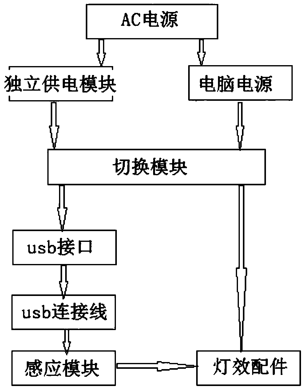
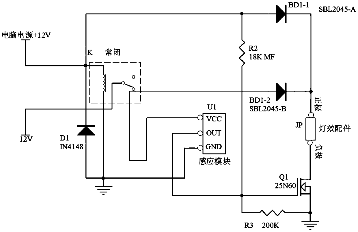
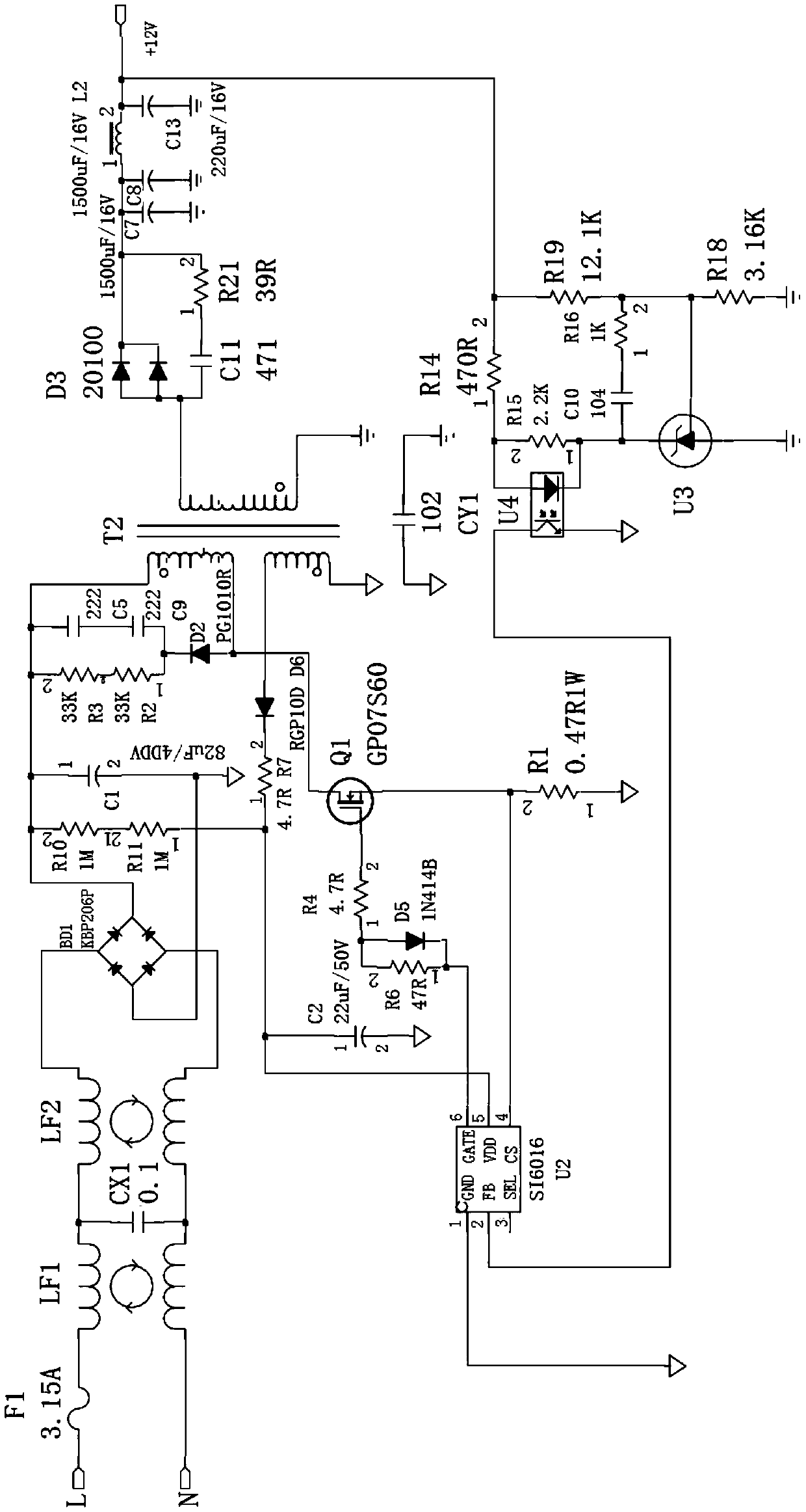
[0025] Such as figure 1 As shown, the power supply switching device for automatically sensing and controlling lighting effects of the present invention includes a computer power supply, an independent power supply module connected to the AC input end of the computer power supply, a switching module, a sensing module and lighting effect accessories of a computer host. The lighting effect accessories of the computer host include lighting and accessories that can be provided with DC power such as ambient lights, LOGO lights, and fan lights inside the host. The computer power supply and the independent power supply module are respectively connected to the switching module, so that the power supply can be flexibly switched between the computer power supply and the independent power supply module. Accessories; when the host computer is turned off, the invention enables the lamp ...


PUM


Abstract

The invention discloses a power supply and switching device for automatically sensing and controlling a lamp effect. The power supply and switching device comprises a computer power supply, an independent power supply module connected with an AC input end of the computer power supply, a switching module, an induction module and a computer host lamp effect accessory. The computer power supply and the independent power supply module are respectively connected with the switching module, one path of the switching module is respectively connected with the computer host lamp effect accessory throughthe sensing module, and the other path is respectively connected with the computer host lamp effect accessory. When the computer host is in a shutdown state, under the control of the switching module, the independent power supply module supplies power to the computer host lamp effect accessory, and the sensing module controls the on-off of the computer host lamp effect accessory. When the host isstarted, under the control of the switching module, the computer power supply directly supplies power to the lamp effect accessories of the computer host. The cool lamp effect of the host can be displayed without starting up the host, so that unnecessary waste is greatly reduced, more convenience is provided for users to save energy and electricity, and clearer and more intelligent user experience is provided.

Description

technical field [0001] The invention relates to a power supply and switching device for automatically sensing and controlling lamp effects, which is mainly used for sensing and controlling ambient lamps, LOGO lamps, fan lamps and other lamp accessories in a computer main box, and belongs to the technical field of computer accessories. Background technique [0002] Computer power supply is a device that converts 220 volts (V) alternating current into direct current, and is specially used to supply power to computer accessories such as CPU, motherboard, hard disk, memory stick, graphics card, optical drive, etc. component. [0003] At present, all computer power supplies on the market are just ordinary accessories with lighting effects such as ambient lights, LOGO lights, and fan lights that supply power to the host. The lighting effect is realized by being close to a certain distance, so the host with the above structure cannot be well connected with the smart products that ...

Claims


Application Information

Patent Timeline
IPC IPC(8): G06F1/26
Inventor 莫伙友
Owner FOSHAN PARTNERS UNIFLY ELECTRONICS
Learn More