
An automatic displacement mechanism of a tightening machine

A technology of displacement mechanism and tightening machine, which is used in metal processing equipment, metal processing, manufacturing tools, etc., can solve the problems of narrow space, unstable output torque, and alarm and shutdown of the tightening machine, so as to improve the automation of equipment and reduce labor. Strength, the effect of improving production efficiency

Active Publication Date: 2020-11-24
中国科学院沈阳计算技术研究所有限公司
View PDF5 Cites 0 Cited by
  • Summary
  • Abstract
  • Description
  • Claims
  • Application Information

AI Technical Summary

Problems solved by technology

For three types of engine cylinder heads, the tightening machine for tightening 28 double camshaft cover bolts, the technical difficulties of the tightening shaft displacement of the tightening machine are as follows: ①The arrangement of the 28 tightening shafts is compact and the space is narrow. After the displacement, there must be a gap of 1-2mm between the closest contact parts between the two tightening shafts, otherwise the two tightening shafts will interfere with each other and cause the overload alarm to cause the tightening machine to stop; It should not be larger than 0.75mm, otherwise the tightening shaft will cause an overtime alarm due to misalignment; ③The tightening shaft must be firmly fixed when the tightening action is performed, and the loosening of the tightening shaft will cause the output torque to be unstable, and the torque overload will cause the tightening machine to alarm and stop

Method used


Image

  • An automatic displacement mechanism of a tightening machine
  • An automatic displacement mechanism of a tightening machine
  • An automatic displacement mechanism of a tightening machine

Examples


Embodiment Construction

[0036] In order to make the object, technical solution and advantages of the present invention clearer, the present invention will be described in detail below in conjunction with the accompanying drawings and specific embodiments.

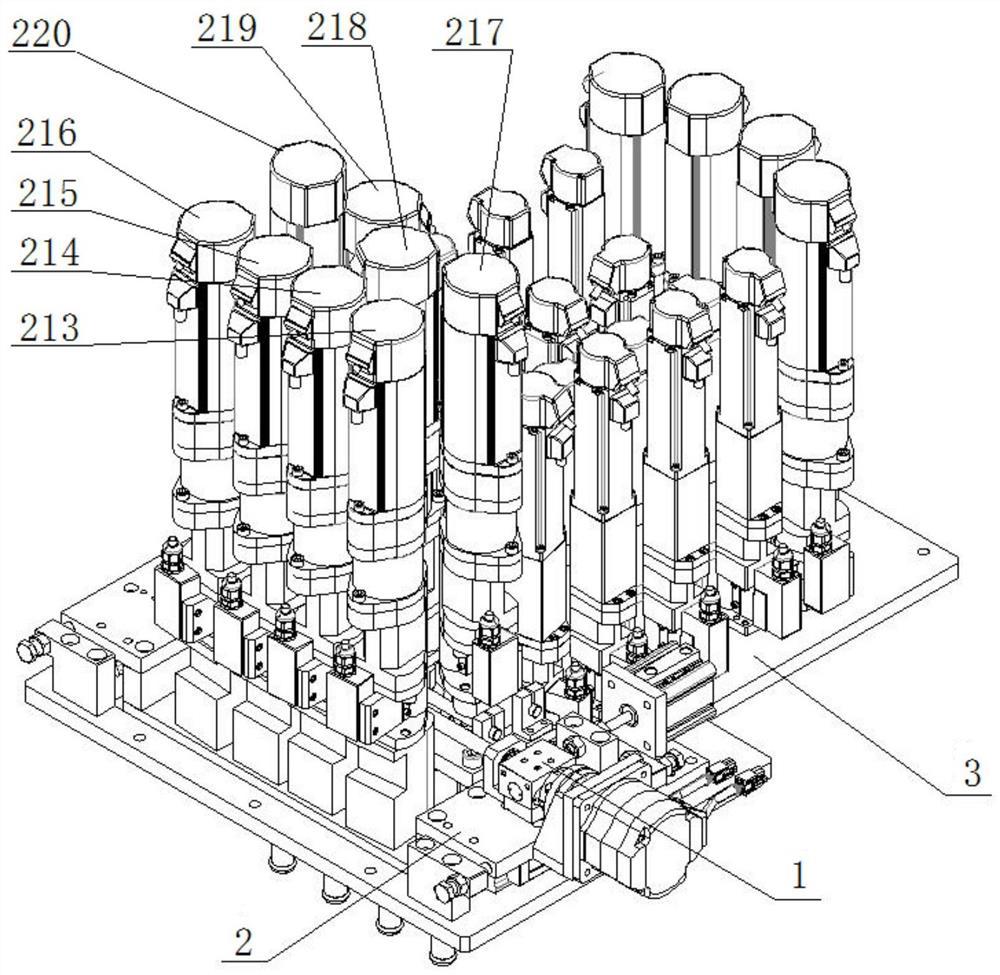
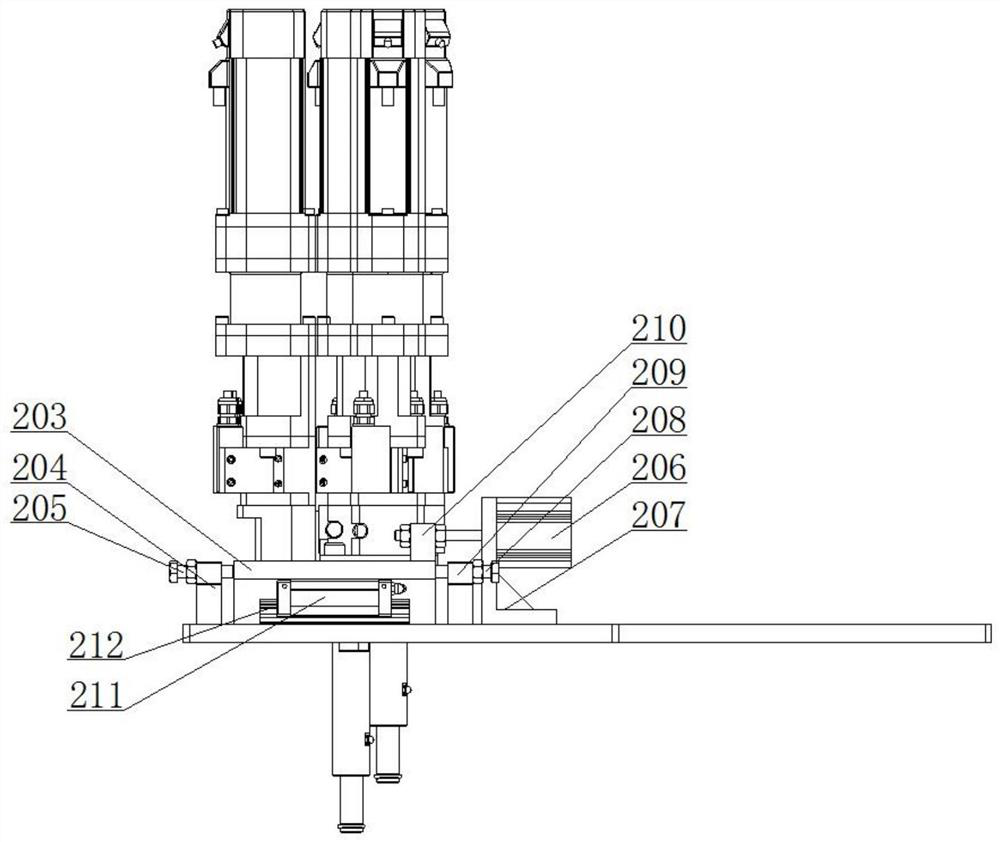
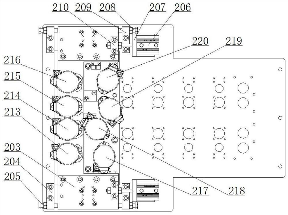
[0037] like figure 1 As shown, a tightening machine automatic displacement mechanism provided by the present invention includes a tightening machine positioning base plate 3, an eight-axis overall displacement mechanism 2, an independent displacement mechanism 1 for the seventh axis, and eight tightening axes, wherein the eight-axis overall displacement mechanism The positioning mechanism 2 is arranged on the positioning base plate 3 of the tightening machine, and the independent displacement mechanism 1 of the eight tightening shafts and the seventh axis is arranged on the eight-axis overall displacement mechanism 2 . The eight tightening shafts are No. 1 tightening shaft 213, No. 2 tightening shaft 214, No. 3 tightening shaft 215, No. 4 tighteni...


PUM


Abstract

The invention belongs to the technical field of automobile engine manufacturing, and particularly relates to an automatic position-changing mechanism of a tightening machine. The automatic position-changing mechanism of the tightening machine comprises a tightening machine positioning base plate, an eight-shaft integral position-changing mechanism, a seventh shaft independent position-changing mechanism and eight tightening shafts, wherein the eight-shaft integral position-changing mechanism is arranged on the tightening machine positioning base plate, the eight tightening shafts and the seventh shaft independent position-changing mechanism are arranged on the eight-shaft integral position-changing mechanism, the eight tightening shafts are arranged in a double-row mode, wherein the seventh tightening shaft can move in the longitudinal direction, the seventh shaft independent position-changing mechanism provides power for the seven tightening shaft to move in the longitudinal direction, and the eight-shaft integral position-changing mechanism is used for driving the eight tightening shafts and the seventh shaft independent position-changing mechanism to move in the transverse direction. According to the automatic position-changing mechanism of the tightening machine, the eight-shaft integral position-changing mechanism and the seventh shaft independent position-changing mechanism can move and position automatically, rapidly and effectively, so as to complete screwing and tightening of double camshaft covers in various engine cylinder heads.

Description

technical field [0001] The invention belongs to the technical field of automobile engine manufacturing, in particular to an automatic displacement mechanism of a screwing machine. Background technique [0002] In the machinery manufacturing industry, screwing machine equipment is widely used, especially in the automobile engine manufacturing process, which has an irreplaceable role. The stable torque output and high-efficiency synchronization of the tightening machine can reduce production costs, labor intensity and improve production efficiency. The specialization of tightening machine equipment in the automotive industry is very strong, and the tightening positions involved are relatively concentrated, basically engine block assembly and cylinder head assembly are the most common, and the difficulty is mainly in the displacement processing when one machine has multiple types and one machine has multiple positions. For three types of engine cylinder heads, the tightening m...

Claims


Application Information

Patent Timeline
Patent Type & Authority Patents(China)
IPC IPC(8): B23P19/06
Inventor 夏筱筠周勇宋佳杨勇张博闻
Owner 中国科学院沈阳计算技术研究所有限公司
Learn More