Infusion device driven by piezoelectric stacks

A technology of an infusion device and a piezoelectric stack, applied in the field of medical devices, can solve the problems of unfavorable drug absorption and utilization, increase the burden on the heart, shorten the infusion time, etc. therapeutic effect

CN109821093AActive Publication Date: 2019-05-31ZHEJIANG NORMAL UNIVERSITY
17 Cites 0 Cited by

Patent Information

Authority / Receiving Office
CN · China
Patent Type
Applications(China)
Current Assignee / Owner
Publication Date
2019-05-31

Smart Images

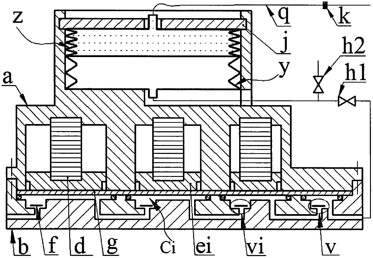
  • Figure 1
    Figure 1
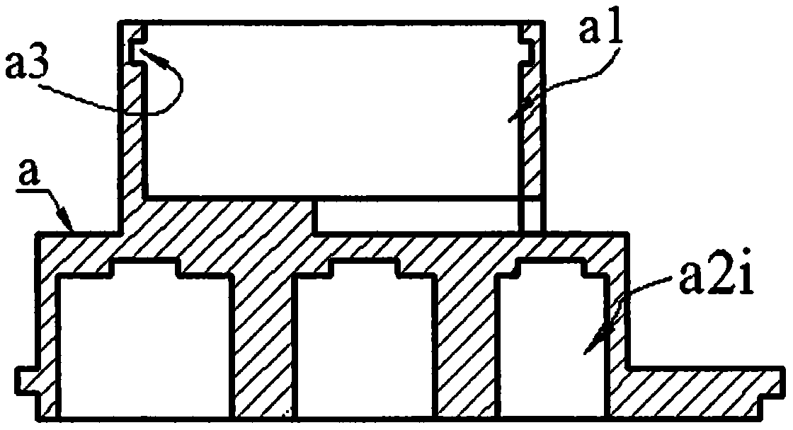
  • Figure 2
    Figure 2
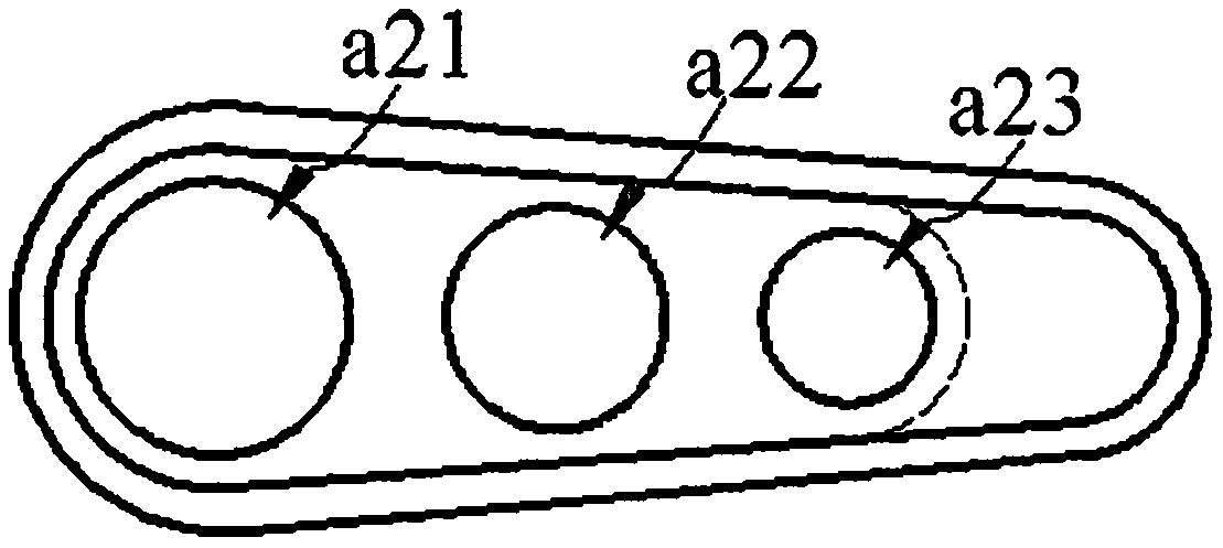
  • Figure 3
    Figure 3
Patent Text Reader

Abstract

The invention relates to an infusion device driven by piezoelectric stacks, and belongs to the field of medical apparatuses. A base is provided with outlet and inlet holes, an outlet cavity and at least two sinking cavities with unequal diameters, the diameters of the sinking cavities are gradually reduced from left to right, and inlet cavities and air outlet holes are formed in the bottom walls of the sinking cavities; the inlet and outlet cavities and valves installed in the inlet and outlet cavities form inlet and outlet valves respectively; guide holes which have the same number and diameter as those of the sinking cavities respectively are formed in the bottom of a main device body, the main device body is installed on the base, diaphragms are pressed on the base, and the guide holesand the sinking cavities are symmetrically formed in the two sides of each diaphragm; the piezoelectric stacks in the guide holes press pistons on the diaphragms; the diaphragms press sealing rings inthe sinking cavities to constitute compression cavities which are connected in series; a bag cavity internally provided with an airbag and a medicine bag is formed in the top of the main device body,and a baffle is installed at the end of the side wall of the bag cavity; a liquid outlet tube of the medicine bag is provided with a flow adjusting valve and a syringe needle, an air inlet tube of the airbag is connected with the outlet hole of the base, and a switching valve and a deflating valve are arranged on an air inlet tube of the airbag. During work, the deformation directions of the diaphragms in every two adjacent compression cavities are opposite.
Need to check novelty before this filing date? Find Prior Art

Description

technical field

[0001] The invention belongs to the field of medical equipment, and in particular relates to a transfusion device driven by a piezoelectric stack. Background technique

[0002] Injection mainly includes intravenous injection, intramuscular injection and subcutaneous injection. Intravenous injection is also called infusion drug administration. Most of the existing infusion devices are composed of infusion bottles, infusion tubes and infusion stands. This infusion mode will bring many problems in actual use: the flow rate is adjusted manually, and the flow control accuracy is not enough; the infusion bottle needs to be held high by others when the patient walks or goes to the toilet, which is inconvenient to move and the height of the infusion bottle is not high enough. Make the blood flow back; the patient or the nursing staff need to watch for a long time, if the infusion is not found in time, it may cause an accident; the liquid medicine is in contact with ...

Examples

Embodiment Construction

[0013] The base b is provided with an inlet hole b1, at least two sink chambers b2i with different diameters, an outlet chamber b3 and an outlet hole b6, the diameters of the sink chamber b2i decrease successively from left to right, and the bottom wall of the sink chamber b2i is provided with The inlet b4 and the air outlet b5, the inlet b4 of the leftmost sink chamber b2i is connected with the inlet b1, the air outlet b5 of the rightmost sink b2i is connected with the outlet b6 through the outlet b3, and the other two adjacent sink chambers The inlet b4 and the air outlet b5 of b2i are connected to each other: the inlet b4 and the outlet b3 and the valve plate f installed in them constitute the inlet valve vi and the outlet valve v respectively, and the valve f is a cantilever beam valve or a disc valve; the main body The bottom of a is provided with guide holes a2i equal in number and diameter to the sink cavity b2i; the main body a is installed on the base b through screws ...