Combined suction type plane cascade experimental device

A combination of suction and experimental device technology, applied in non-variable pumps, pump control, machine/engine, etc., can solve problems such as inability to pump, cumbersome installation process of experimental devices, etc.

Inactive Publication Date: 2019-05-31
NORTHWESTERN POLYTECHNICAL UNIV
View PDF6 Cites 3 Cited by
  • Summary
  • Abstract
  • Description
  • Claims
  • Application Information

AI Technical Summary

Problems solved by technology

[0006] In order to avoid the deficiencies of the prior art, the present invention proposes a combined suction type planar cascade experimental device on the basis of only adding a layer of suction cover and not changing the original blade shape line, which improves the

Method used


Image

  • Combined suction type plane cascade experimental device
  • Combined suction type plane cascade experimental device
  • Combined suction type plane cascade experimental device

Examples


Embodiment Construction

[0040] The embodiments described below by referring to the figures are exemplary and are intended to explain the present invention and should not be construed as limiting the present invention.

[0041] In describing the present invention, it should be understood that the terms "center", "longitudinal", "transverse", "length", "width", "thickness", "upper", "lower", "front", " Orientation indicated by rear, left, right, vertical, horizontal, top, bottom, inside, outside, clockwise, counterclockwise, etc. The positional relationship is based on the orientation or positional relationship shown in the drawings, which is only for the convenience of describing the present invention and simplifying the description, rather than indicating or implying that the referred device or element must have a specific orientation, be constructed and operated in a specific orientation, Therefore, it should not be construed as limiting the invention.

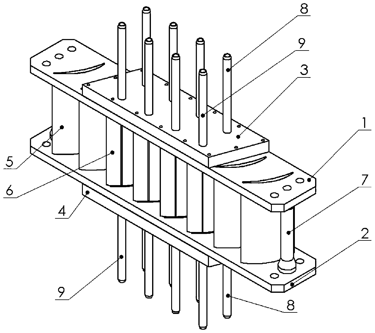
[0042] This implementation regulation is a c...


PUM


Abstract

The invention discloses a combined suction type plane cascade experimental device which comprises a first grid plate, a second grid plate, a first suction hood, a second suction hood, a non-suction blade, a suction blade, a grid plate rod, a suction surface suction rod and an end wall suction rod, wherein the first suction hood and the second suction hood are of two platy structures in mirror symmetry and are fixed in the centers of the outer end faces of the first grid plate and the second grid plate separately; a plurality of end wall suction cavities are formed between the first suction hood and the first grid plate; a plurality of suction surface suction cavities are formed between the second suction hood and the second grid plate; and the end wall suction rod and the suction surface suction rod at the mounting outer ends are adopted to guide boundary layer low-energy fluid out. The combined suction type plane cascade experimental device overcomes the difficulty in the prior art that end wall suction and suction surface suction cannot be carried out simultaneously, realizes the purpose of independently controlling the suction flow rate of the end wall and the blade suction surface, meets the experimental demand of flow matching of two suction grooves under different working conditions, and can fully and completely suck the low-energy fluid in the end wall boundary layer.

Description

technical field [0001] The invention belongs to the field of aeroengine high-load compressor cascade aerodynamic experiments, in particular to a combined suction plane cascade experimental device. Background technique [0002] Boundary layer suction technology is a method of reducing or removing boundary layer flow separation by sucking low-energy fluid at key positions inside the cascade channel, which can increase the pressure ratio and efficiency of a single stage of the compressor, and make the compressor It can maintain high working efficiency and stable working state under the conditions of large blade load and strong reverse pressure gradient, and has achieved relatively common research and application in the field of engine flow separation control. However, with the increase of the compressor load, the flow separation in the cascade channel becomes worse, not only the separation of the suction surface boundary layer, but also the influence of the large recirculation ...

Claims


Application Information

Patent Timeline
IPC IPC(8): F04D27/00
Inventor 梁田刘波
Owner NORTHWESTERN POLYTECHNICAL UNIV
Why Eureka
Try Eureka