
Executing mechanism, control valve and valve control system

A valve control and actuator technology, applied in the field of control valves, can solve problems such as inability to diagnose valve faults, failure of actuators, etc.

Active Publication Date: 2019-05-31
SIEMENS SWITZERLAND
View PDF2 Cites 2 Cited by
  • Summary
  • Abstract
  • Description
  • Claims
  • Application Information

AI Technical Summary

Problems solved by technology

Existing actuators can usually only acquire sensor signals containing the actuator’s action data and send them to the control center. The control center diagnoses whether the valve is faulty by comparing it with the preset data, for example, due to the failure of the valve The rod is stuck, causing the actuator to fail to achieve the intended action
This actuator can only diagnose the symptoms of the valve, not the potential failure of the valve

Method used


Image

  • Executing mechanism, control valve and valve control system
  • Executing mechanism, control valve and valve control system
  • Executing mechanism, control valve and valve control system

Examples


Embodiment Construction

[0045] In order to have a clearer understanding of the technical features, purposes and effects of the invention, the specific embodiments of the present invention are now described with reference to the accompanying drawings, in which the same reference numerals represent components with the same or similar structures but the same functions.

[0046] In this article, "schematic" means "serving as an example, example or illustration", and any illustration or implementation described as "schematic" should not be interpreted as a more preferred or more advantageous Technical solutions.

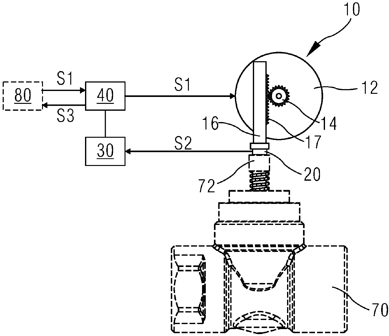
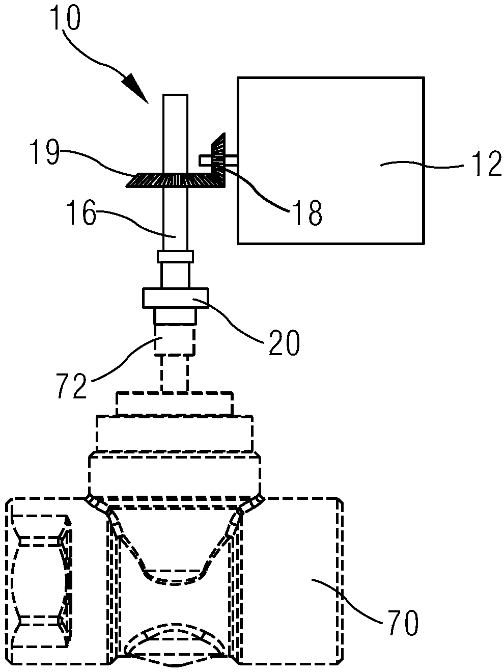
[0047] figure 1 It is a structural schematic diagram of a schematic implementation of the actuator used to illustrate the control valve, refer to figure 1 , the control system includes a control center 80, the control center 80 can send a control signal S1, and the control center 80 can also receive a diagnosis signal S3 and analyze and diagnose it. The control valve includes a valve 70, the v...


PUM


Abstract

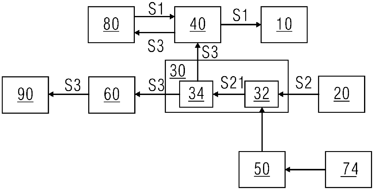
The invention relates to an executing mechanism of a control valve of a valve control system. The executing mechanism comprises a driving unit (10), a sensor unit (20), a data processing unit (30) anda communication control unit (40), wherein the driving unit can receive a control signal (S1) and drive a valve rod to rotate; the sensor unit is arranged on the driving unit and can sense the driving force applied to the valve rod when the driving unit drives the valve rod to move and generate an initial diagnosing signal (S2); the data processing unit can receive the initial signal, perform signal conditioning and generate a diagnosing signal (S3); the communication control unit can receive the control signal, can transmit the control signal to the driving unit, and can also receive the diagnosing signal and transmit the diagnosing signal to a control center (80); and the executing mechanism can transmit the data of the driving force of the driving mechanism on the valve rod to the control center to diagnose the potential failure of a valve. The invention also provides the control valve comprising the executing mechanism and the valve control system.

Description

technical field [0001] The invention relates to the technical field of control valves, in particular to an actuator of a control valve of a control system, a control valve with an actuator, and a control system. Background technique [0002] A control valve includes a valve and an actuator, and the actuator drives the valve through action. In order to meet the needs of the market, the actuator usually needs to have a diagnostic function. Existing actuators can usually only acquire sensor signals containing the actuator’s action data and send them to the control center. The control center diagnoses whether the valve is faulty by comparing it with the preset data, for example, due to the failure of the valve The rod is stuck, causing the actuator to fail to achieve the intended action. This kind of actuator can only diagnose the symptoms that the valve has appeared, and cannot diagnose the potential failure of the valve. Contents of the invention [0003] The purpose of t...

Claims


Application Information

Patent Timeline
IPC IPC(8): F16K31/04F16K31/53
CPCG05B19/042G05B2219/33326G05B2219/45006F15B19/005F16K37/0083F15B15/1457F15B2211/865F15B19/007G05B15/02F15B2211/76F15B15/202
Inventor 王力袁勇蓝培
Owner SIEMENS SWITZERLAND
Learn More