Ultra wide band electric field probe using U-shaped structure

An ultra-broadband, U-shaped technology, applied in the field of U-shaped electric field probe structure, to achieve the effect of improving the measurement of weak electric field signals and ultra-broadband testing, high sensitivity, and ensuring accuracy

Active Publication Date: 2019-06-14
BEIHANG UNIV
View PDF9 Cites 3 Cited by
  • Summary
  • Abstract
  • Description
  • Claims
  • Application Information

AI Technical Summary

Problems solved by technology

[0004] In order to overcome the deficiencies of existing near-field electric field probes, the purpose of the present invention is to provide an ultra-wideband U-shaped electric field probe for near-field testing, which can effectively solve the problem of testing spatial field strength distribution in broadband

Method used


Image

  • Ultra wide band electric field probe using U-shaped structure
  • Ultra wide band electric field probe using U-shaped structure
  • Ultra wide band electric field probe using U-shaped structure

Examples


Embodiment Construction

[0018] The present invention will be further described in detail below in conjunction with the accompanying drawings.

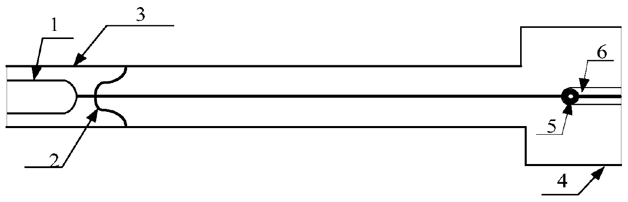
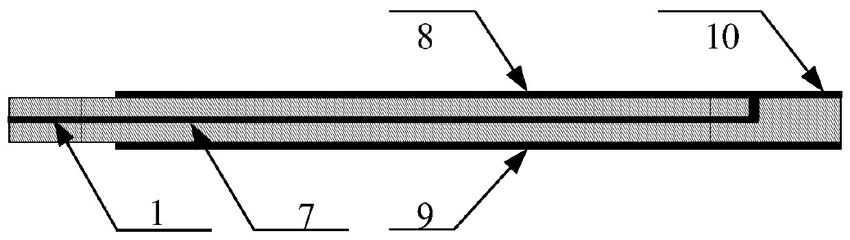
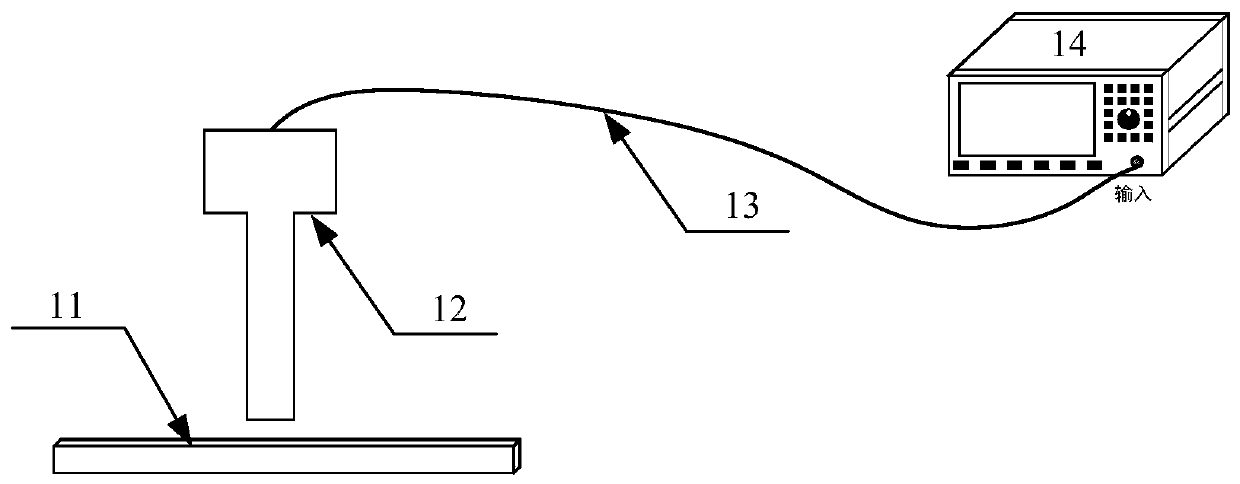
[0019] Such as figure 1 figure 2 As shown, this example provides an ultra-broadband electric field probe with a U-shaped structure for near-field testing, including a U-shaped signal line 1, an arc edge 2, a narrow handle end of the probe 3, a wide handle end 4 of the probe, and a connecting hole 5. Isolation slot 6, middle layer signal line 7, top layer reference plane 8, bottom layer reference plane 9, top layer signal line 10, tested platform 11, electric field probe 12, coaxial cable 13 and test equipment 14.

[0020] The U-shaped signal line 1 forms a stripline structure between the top reference plane 8 and the bottom reference plane 9, the U-shaped signal line is located at one end of the narrow handle end 3 of the probe, and the U-shaped signal line 1 at the open end The two arms are distributed symmetrically along the center line of the probe plan...


PUM


Abstract

The invention discloses an ultra wide band electric field probe using a U-shaped structure. The ultra wide band electric field probe includes arc edge reference planes, a U-shaped signal line, an intermediate signal line and a top layer signal line. The arc edge reference planes include a top layer reference plane and a bottom layer reference plane, and the top layer reference plane and the bottomlayer reference plane are correspondingly of symmetrical similar 'T' shape structures in the central line of the plane of the probe. The U-shaped signal line is located between the top layer reference plane and the bottom layer reference plane, and a narrow handle end located on the intermediate layer of the probe is a transmission line of a strip line structure. Two arms of the open end of the U-shaped signal line are distributed symmetrically in the center line of the plane of the probe. The arc end of the U-shaped signal line is connected with the intermediate layer signal line, and the intermediate layer signal line is connected to the top layer signal line through a connecting hole. The ultra wide band electric field probe has the characteristics of ultra wide band and high sensitivity, the defect that in a traditional test, signals of weak electric fields and ultra wide band testing are not measured are effectively improved, and veracity of testing results is ensured.

Description

【Technical field】 [0001] The invention belongs to the field of electromagnetic field testing, and particularly relates to a U-shaped electric field probe structure for ultra-wideband near-field testing with a frequency bandwidth of 9KHz-40GHz, that is, the near-field electric field distribution parameters of the equipment under test can be obtained by performing near-field testing with the probe. 【Background technique】 [0002] With the rapid development of science and technology, the wide application of large-scale integrated circuits and the increasing operating frequency of circuits, every module and even every section of wiring in electrical equipment may be a source of electromagnetic interference. Electromagnetic interference not only affects the normal operation of the system, but also may cause serious accidents in severe cases. In recent years, countries around the world are actively formulating standards and norms to promote the effective protection of electromagne...

Claims


Application Information

Patent Timeline
Patent Type & Authority Applications(China)
IPC IPC(8): G01R29/14
Inventor 阎照文闵争刘伟
Owner BEIHANG UNIV
Why Eureka
Try Eureka