
A method and system for shortening the action delay of in-situ failure protection

A failure protection and action technology, applied in emergency protection circuit devices, electrical components, etc., can solve problems such as long delay in failure protection action

Active Publication Date: 2021-07-06
NARI TECH CO LTD +5
View PDF7 Cites 0 Cited by
  • Summary
  • Abstract
  • Description
  • Claims
  • Application Information

AI Technical Summary

Problems solved by technology

When the line protection sending end receives the input from the failure protection action of the adjacent device, it requires the remote tripping input and the remote transmission input to be confirmed after a delay of 20ms before being sent to the opposite line protection through the fiber channel, and the failure protection action is delayed long

Method used


Image

  • A method and system for shortening the action delay of in-situ failure protection
  • A method and system for shortening the action delay of in-situ failure protection
  • A method and system for shortening the action delay of in-situ failure protection

Examples


Embodiment 1

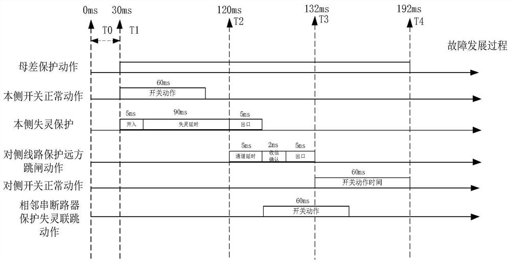
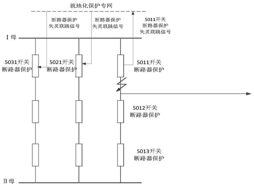
[0072]Embodiment 1: In this embodiment, the action sequence and delay distribution of the present invention are analyzed by taking the occurrence of a fault on the bus on the local side as time 0. After 30ms after a fault occurs on the busbar, the busbar protection acts and exits to start the failure protection of the circuit breaker protection. The failure protection action time of circuit breaker protection is set to 90ms. 90ms is considered based on the fact that the main protection operates in 30ms and the switch fails to trip in 60ms. That is, the circuit breaker protection will judge that the circuit breaker has failed to trip after 90ms after receiving the protection trip switch, and the circuit breaker failure protection will be activated. In the on-site circuit breaker protection and line protection designed in the present invention, the switch signal between the devices interacts through the on-site protection special network. From the failure of the busbar to the o...

Embodiment 2

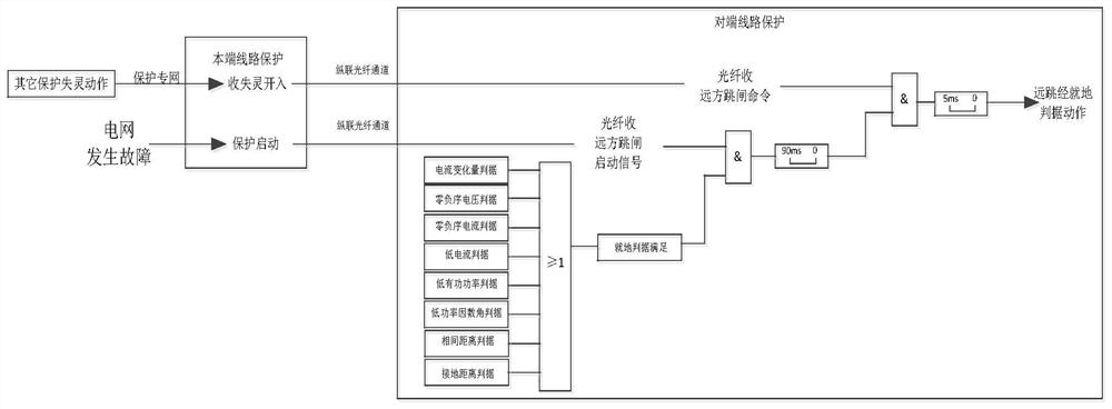
[0078] Embodiment 2: In this embodiment, the long-jump passing fault criterion time and the long-distance jump not passing the fault criterion time are set to 90ms and cannot be adjusted: if a fault occurs on the opposite side, the main protection switch fails to trip in 60ms, and the failure protection returns in 30ms design. For the side protection that receives the remote trip start command, if any remote trip local criterion meets the action condition and the timing exceeds 90ms, it can be determined that the switch on the opposite side of the line has failed.

[0079] After the line protection at the local end receives the failure signal sent by the circuit breaker protection through the local protection network, the failure protection action signal is sent to the opposite end in the form of "remote transmission 1" through the longitudinal fiber channel. If any of the remote trip local criteria of the peer line protection satisfies the action condition and the timing of 9...


PUM


Abstract

The invention proposes a method for shortening the time delay of in-situ failure protection action. Based on the cooperation of circuit breaker protection and line protection, the interaction of failure action signals of each protection device in this station is realized through the in-situ protection special network, and the circuit breaker protection configuration The side switch failure joint trip and the optimized failure protection algorithm realize the fast fault isolation of the switch failure on the transmission line side, and the fast remote trip process of the line protection configuration and the remote trip local criterion of increasing the phase distance and the grounding distance are used to realize the fault isolation. Quick cut-off of the end-to-end switch of the transmission line. Through this set of technical solutions, the time for the main protection action-failure protection action on this side to start the switch on the opposite side of the long-jump line can be shortened to less than 200 milliseconds, ensuring that no DC commutation failure occurs, and reducing the impact of AC system faults on the DC system impact, thereby improving the safety and stability of the AC-DC interconnection system.

Description

technical field [0001] The invention belongs to the technical field of power system failure protection, and in particular relates to a method for optimizing the action flow of in-situ failure protection, shortening the time delay of protection action, and reducing the time for isolation and failure of in-situ protection by coordinating circuit breaker protection and line protection. Background technique [0002] The 500kV circuit breaker failure protection of the domestic AC power grid is configured according to the circuit breaker switch, that is, the circuit breaker protection device is used to realize the failure protection function. But for the failure of the system failure switch, according to the existing setting regulations, the circuit breaker failure protection action time is about 200-250ms. After the failure protection action, the opposite-side switch is far-jumped through the line protection, and the circuit breakers installed in the same bus in adjacent strings ...

Claims


Application Information

Patent Timeline
Patent Type & Authority Patents(China)
IPC IPC(8): H02H7/26
Inventor 吴通华陈国洲姚刚郑玉平王小红裘愉涛汪冬辉洪丰郑小江余洪江源侯小凡
Owner NARI TECH CO LTD
Learn More