
A calibration method of laser two-dimensional ranging sensor

A technology of distance measuring sensor and calibration method, which is applied in the direction of instruments, radio wave measurement systems, etc., which can solve the problems of ignoring the accuracy of the code disc and the inability to eliminate the influence of the code disc, and achieve the effect of reducing the total time of system error calibration

Active Publication Date: 2021-03-12
SUZHOU UNION INTELLIGENT TECH CO LTD
View PDF9 Cites 0 Cited by
  • Summary
  • Abstract
  • Description
  • Claims
  • Application Information

AI Technical Summary

Problems solved by technology

This method relies on the motor itself, requires the motor itself to have high performance, ignores the accuracy of the code disc, and cannot eliminate the impact of the error of the code disc

Method used


Image

  • A calibration method of laser two-dimensional ranging sensor
  • A calibration method of laser two-dimensional ranging sensor
  • A calibration method of laser two-dimensional ranging sensor

Examples


Embodiment Construction

[0062] The present invention will be further described below in conjunction with the accompanying drawings and specific embodiments, so that those skilled in the art can better understand the present invention and implement it, but the examples given are not intended to limit the present invention.

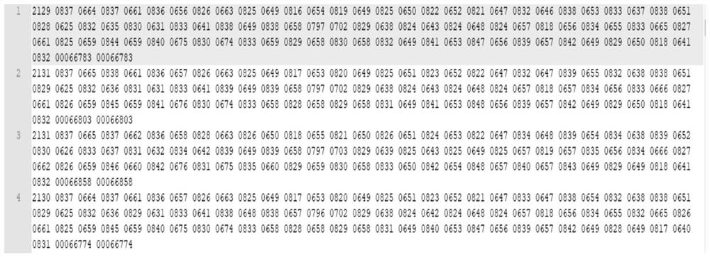
[0063] This embodiment discloses a calibration method for a laser two-dimensional ranging sensor, including angle calibration and distance calibration. Angle calibration is divided into two parts: a code disc calibration algorithm and an angle real-time calibration algorithm. The angle between the teeth is not uniform, and there is a certain error. Our products need to control the angle through the code disc, so the calibration of the code disc is particularly important;

[0064] The code disc calibration algorithm is to calibrate the angle value of each tooth of the code disc when the motor drives the code disc to rotate at a constant speed, including:

[0065] S1.1: When the mot...


PUM


Abstract

A calibration method for a two-dimensional laser ranging sensor, comprising the following steps: insofar as an electric motor is driving an encoding disk to rotate at a uniform speed, performing angle calibration with respect to each tooth of the encoding disk, performing uniform punching between adjacent two teeth, calculating in real-time to acquire a point corresponding to any calibration angle between adjacent two teeth; acquiring measurement points formed at a uniform speed by a two-dimensional laser ranging sensor in a predetermined angle, and acquiring measurements of the distance between each measurement point and the two-dimensional laser ranging sensor, combining this series of measurements per a Kalman filter algorithm and a weighted average filter algorithm to reduce noise; respectively analyzing and quantifying per a statistic fixed-point system error calibration model and a static panoramic system error calibration model the effects that the measuring distance and the rotational speed of the electric motor have in terms of error, and correcting a system error incurred by a discrepancy between the measuring distance and the rotational speed of the electric motor. The method is applicable in the calibration of a two-dimensional laser ranging sensor.

Description

technical field [0001] The invention relates to a calibration method for a laser two-dimensional distance measuring sensor. Background technique [0002] The calibration of the laser two-dimensional ranging sensor can be divided into two parts: distance calibration and angle calibration. [0003] In terms of distance calibration, distance calibration can be divided into two parts: system error calibration and random error calibration. [0004] For the system error, there are mainly two calibration methods at present. The first method is to directly obtain the corresponding relationship between the current real value and the output value through experiments at intervals of a small distance, and form a calibration table. This method has high precision, but it is only suitable for small ranges, and the calibration takes a long time, resulting in a large amount of manpower and time resource consumption, and the calibration efficiency is low, and it is not suitable for large-sc...

Claims


Application Information

Patent Timeline
Patent Type & Authority Patents(China)
IPC IPC(8): G01S7/497
CPCG01S7/4972
Inventor 于成磊宁智文刘慧林
Owner SUZHOU UNION INTELLIGENT TECH CO LTD
Learn More