Multifunctional legume pod removal device
A multi-functional, depod technology, applied in solid separation, sieve, grid, etc., can solve the problems of intermittent discharge, classification, difficult beans and so on
- Summary
- Abstract
- Description
- Claims
- Application Information
AI Technical Summary
Benefits of technology
Problems solved by technology
Method used
Image
Examples
specific Embodiment approach 1
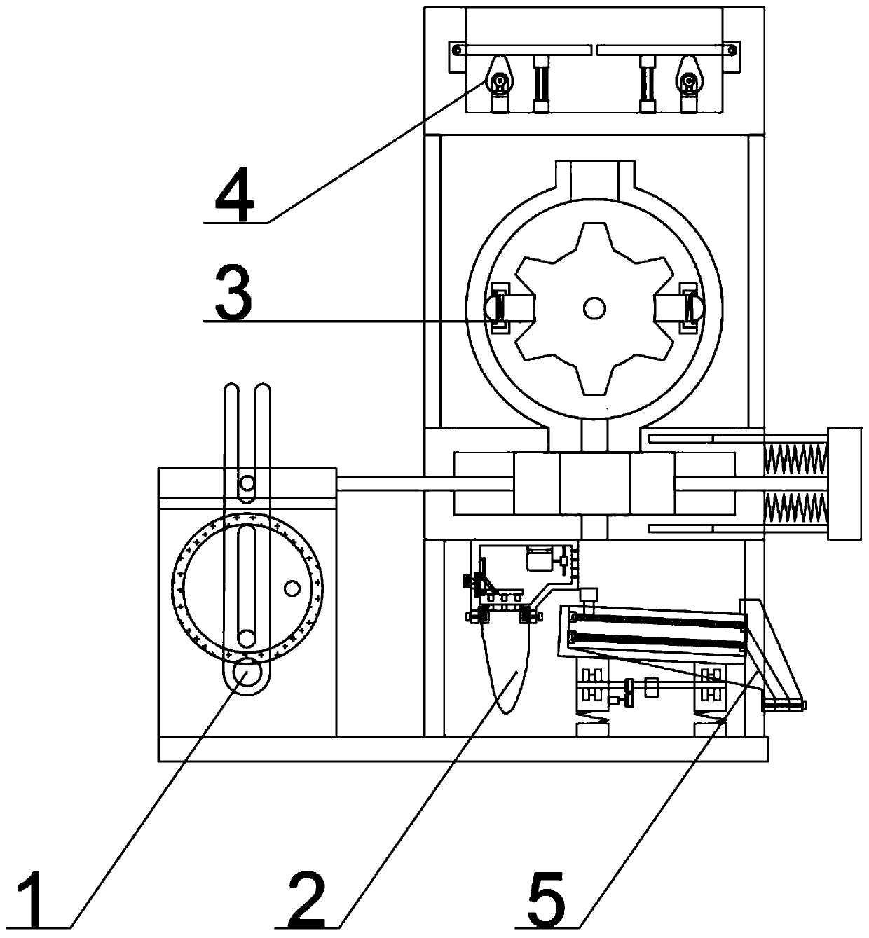
[0037] Combine below figure 1 , figure 2 , image 3 , Figure 4 , Figure 5 , Figure 6 , Figure 7 , Figure 8 , Figure 9 , Figure 10 , Figure 11 , Figure 12 , Figure 13 , Figure 14 , Figure 15 , Figure 16 , Figure 17 , Figure 18 To illustrate this embodiment, the present invention relates to a pod removal device, more specifically a multifunctional bean pod removal device, including an intermittent feeding mechanism 1, a pod collection mechanism 2, a pod removal mechanism 3, and a feeding mechanism 4 , The screening mechanism 5, the equipment can automatically feed, the equipment can remove pods, the equipment can discharge materials intermittently, the equipment can collect pods, the equipment can prevent blockage, and the equipment can classify and screen beans.
[0038] The intermittent feeding mechanism 1 is connected to the pod removal mechanism 3 , the pod collection mechanism 2 is located below the pod removal mechanism 3 , the screening mec...
specific Embodiment approach 2
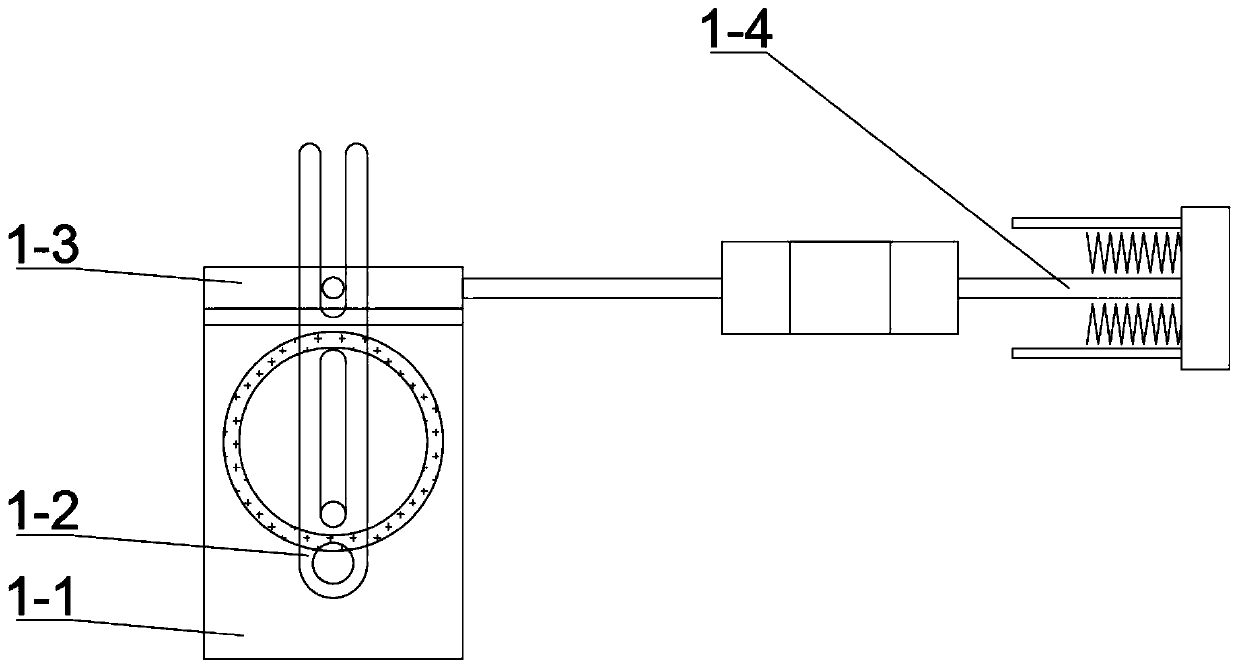
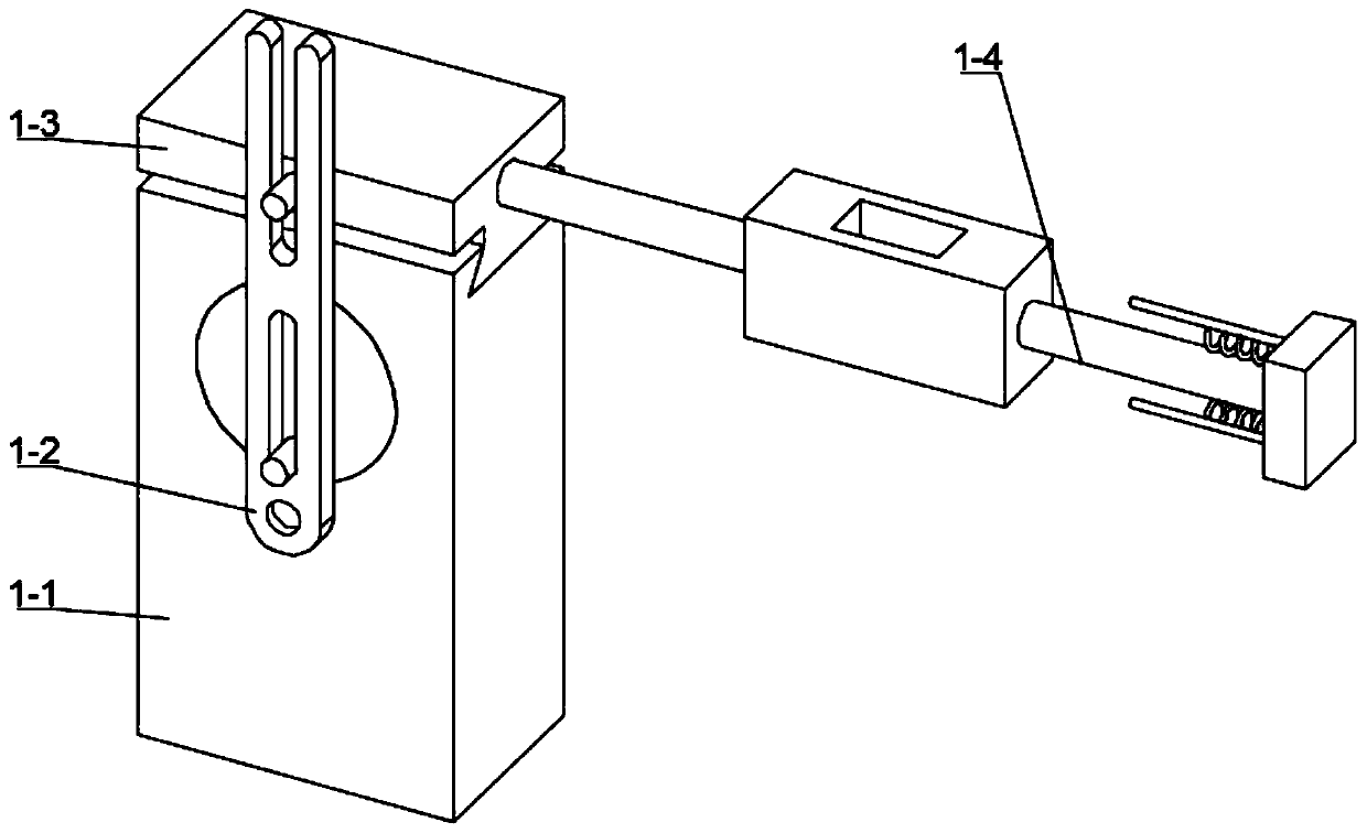
[0040] Combine below figure 1 , figure 2 , image 3 , Figure 4 , Figure 5 , Figure 6 , Figure 7 , Figure 8 , Figure 9 , Figure 10 , Figure 11 , Figure 12 , Figure 13 , Figure 14 , Figure 15 , Figure 16 , Figure 17 , Figure 18 Describe this embodiment, this embodiment will further explain the first embodiment, the intermittent feeding mechanism 1 includes a drive seat mechanism 1-1, a swing rod seat mechanism 1-2, a reciprocating seat mechanism 1-3, and a limit seat mechanism 1-4, the drive seat mechanism 1-1 is hinged with the swing rod seat mechanism 1-2, the drive seat mechanism 1-1 cooperates with the reciprocating seat mechanism 1-3, the swing rod seat mechanism 1-2 and the reciprocating seat mechanism 1- 3 are matched, the limit seat mechanism 1-4 is connected with the reciprocating seat mechanism 1-3; the drive seat mechanism 1-1 includes a seat body with a cylinder groove 1-1-1, a bearing seat 1-1-2, and a rotating protrusion 1 -1-3, rot...
specific Embodiment approach 3
[0042] Combine below figure 1 , figure 2 , image 3 , Figure 4 , Figure 5 , Figure 6 , Figure 7 , Figure 8 , Figure 9 , Figure 10 , Figure 11 , Figure 12 , Figure 13 , Figure 14 , Figure 15 , Figure 16 , Figure 17 , Figure 18 Describe this embodiment, this embodiment will further explain Embodiment 1, the pod collection mechanism 2 includes a cloth bag 2-1, a cloth bag clamping mechanism 2-2, a bellows mechanism 2-3, an anti-blocking mechanism 2-4, a fan 2-5, impeller 2-6, return spring I2-7, cloth bag 2-1 is connected with cloth bag clamping mechanism 2-2, cloth bag clamping mechanism 2-2 is connected with bellows mechanism 2-3, anti-blocking mechanism 2-4 Connected with the bellows mechanism 2-3, the fan 2-5 is set inside the bellows mechanism 2-3, the impeller 2-6 is connected with the fan 2-5, the return spring I2-7 is connected with the blocking mechanism 2-4; the cloth bag clamping mechanism 2-2 includes clamping screw 2-2-1, threaded hol...
PUM
 Abstract
Description
Claims
Application Information
 - R&D
- Intellectual Property
- Life Sciences
- Materials
- Tech Scout
- Unparalleled Data Quality
- Higher Quality Content
- 60% Fewer Hallucinations
Browse by: Latest US Patents, China's latest patents, Technical Efficacy Thesaurus, Application Domain, Technology Topic, Popular Technical Reports.
© 2025 PatSnap. All rights reserved.Legal|Privacy policy|Modern Slavery Act Transparency Statement|Sitemap|About US| Contact US: help@patsnap.com


