Vehicle

A vehicle and body technology, applied in the field of the cooler body, can solve the problems of damage to the cooler body and cooling performance, and achieve the effects of easy assembly and suppression of interference.

Active Publication Date: 2019-08-09
TOYOTA JIDOSHA KK
View PDF11 Cites 0 Cited by
  • Summary
  • Abstract
  • Description
  • Claims
  • Application Information

AI Technical Summary

Problems solved by technology

[0007] However, in a vehicle in which the cooler body is arranged at the lower part of the vehicle, foreign objects such as stones and mud splashed from the road surface come into contact with the cooler body, and the cooling performance may be impaired due to damage to the cooler body or clogged holes.
On the other hand, it is conceivable to arrange the bottom cover on the lower side of the cooler main body. However, when the bottom cover interferes with the unevenness of the road surface and receives an impact from below, the impact load is transmitted to the cooler main body through the bottom cover, and the cooler main body may be damaged

Method used


Image

  • Vehicle
  • Vehicle
  • Vehicle

Examples


Embodiment

[0053] Hereinafter, embodiments of the present invention will be described in detail with reference to the drawings. It should be noted that in the following embodiments, the drawings are appropriately simplified or deformed for explanation, and the dimensional ratio and shape of each part may not be accurately drawn.

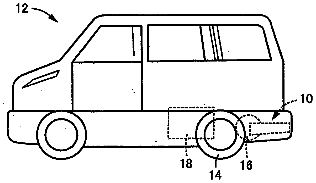
[0054] figure 1 It is a schematic side view of a vehicle 12 mounted with a vehicle cooler device 10 viewed from the left side. The vehicle 12 generates power through a fuel cell and is powered by an electric motor M (refer to figure 2 ) generates driving force, and in a fuel cell type electric vehicle that drives the rear wheels 14 to rotate, the vehicle cooler device 10 is arranged in the vehicle front and rear direction together with the hydrogen tank 16 filled with hydrogen as the fuel of the fuel cell. It is located on the vehicle rear side of the rear wheel 14 . The vehicle cooler device 10 cools oil as a cooling medium by exchanging heat with outside ...


PUM


Abstract

A vehicle is provided. Under the condition that an undercover is attached to the lower side of a cooler body, impact from above is prevented from being transmitted to the cooler body. A gap (s) is provided between the undercover which protect the cooler body against impurities such as splashing mud and the lower surface of the cooler body, so that the damage of the cooler body is prevented when animpact load (Fu) is applied to the undercover. The undercover is provided with an exhaust port for discharging discharged air of the cooler body to the outside through negative pressure; an elastically deformable sealing member is provided for blocking the gap, so that the differential pressure air guide type cooling performance of a vehicle cooling device where the discharged air of the cooler body can be exhausted to the outside through the negative pressure and new outside air can be introduced into the cooler body can be properly obtained in spite of the gap. In another aspect, the effectof restraining the damage of the cooler body caused by the gap can be properly achieved through elastic deformation of the sealing member.

Description

technical field [0001] The present invention relates to a vehicle in which a heat exchange type cooler main body is arranged at a lower portion of the vehicle and attached to a vehicle body. Background technique [0002] There is known a vehicle in which a heat exchange type cooler body through which a cooling medium such as oil or water flows is arranged at a lower portion of the vehicle and attached to a vehicle body. The vehicle described in Patent Document 1 is an example. In a vehicle in which a transaxle for driving the rear wheels is arranged on the rear side of the vehicle center portion, a cooling medium for cooling the transaxle is arranged at the lower part of the vehicle on the rear side of the vehicle. Cooler body for cooling. Moreover, Patent Document 2 describes a cooling technology of a differential pressure air guide type: in order to cool the power supply device by outside air, there is an exhaust passage that becomes negative pressure by the air flow when...

Claims


Application Information

Patent Timeline
Patent Type & Authority Applications(China)
IPC IPC(8): B60K11/04B60K1/00B60R13/08
CPCB60K11/04B60K1/00B60R13/08B60R13/0861B60K2001/003B60K11/08B60K2001/001B60K2001/006B60K11/02B62D25/2072B62D35/02B62D25/24B60K13/02B60K13/04B60K11/06
Inventor 中村康一古川智章高木清式
Owner TOYOTA JIDOSHA KK
Why Eureka
Try Eureka