Connector and its shielding sleeve assembly

A technology for shielding sleeves and connectors, which is applied to parts, connections, and electrical components of connecting devices, and can solve the problems of occupying the axial space of high-voltage through-hole connectors and increasing the axial size of the connectors.

Active Publication Date: 2021-06-04
CHINA AVIATION OPTICAL-ELECTRICAL TECH CO LTD
View PDF16 Cites 0 Cited by
  • Summary
  • Abstract
  • Description
  • Claims
  • Application Information

AI Technical Summary

Problems solved by technology

However, the inner shielding sleeve needs to axially press the first elastic member to be electrically connected to the mounting panel, and axially press the second elastic member to be electrically connected to the outer shielding sleeve. The elastic member needs to occupy the axial space of the high-voltage through-hole connector , thus increasing the axial dimension of the connector

Method used


Image

  • Connector and its shielding sleeve assembly
  • Connector and its shielding sleeve assembly
  • Connector and its shielding sleeve assembly

Examples


Embodiment 2

[0036] Embodiment 2 of the connector of the present invention differs from Embodiment 1 in that: in Embodiment 1, the shielding ring is fixedly assembled with the shielding sleeve separately through the annular body. In this embodiment, the annular body of the shielding ring is welded to the shielding sleeve superior.

Embodiment 3

[0037] Embodiment 3 of the connector of the present invention differs from Embodiment 1 in that: in Embodiment 1, the annular body is separately fixed and assembled with the inversion edge of the shielding sleeve through the flanging. In this embodiment, the inversion of the shielding sleeve A slot is provided on the inner peripheral surface of the ring, and a protrusion protruding radially is provided on the annular body, and the protrusion cooperates with the slot to make the shielding ring and the shielding sleeve separately and fixedly assembled.

[0038] Embodiment 4 of the connector of the present invention differs from Embodiment 1 in that: in Embodiment 1, the rear end of the shielding sleeve is provided with an eversion edge, and the rear sealing ring cooperates with the eversion edge. In this embodiment , the valgus edge of the shielding sleeve is omitted, the rear end of the shielding sleeve has a thickened portion with an increased radial thickness, and the rear sid...

Embodiment 5

[0039] Embodiment 5 of the connector of the present invention differs from Embodiment 1 in that: in Embodiment 1, the rear end of the shrapnel is bent toward the shielding sleeve, and the middle part of the shrapnel forms an arc-shaped pressing portion. In this embodiment, the shrapnel The rear end is provided with a circular protrusion extending radially along the shielding sleeve, and the shrapnel is elastically press-fitted with the metal shell through the circular protrusion.


PUM


Abstract

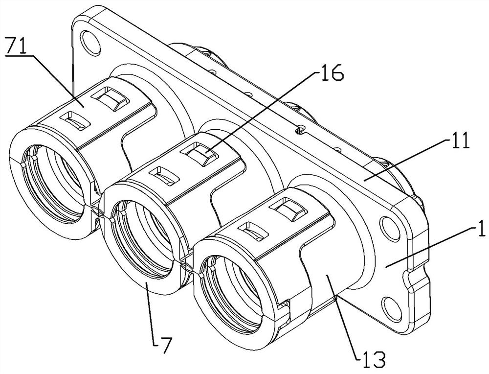
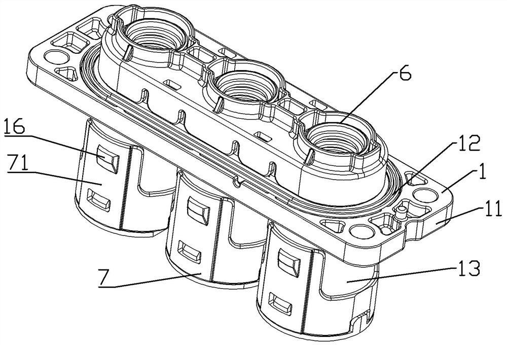
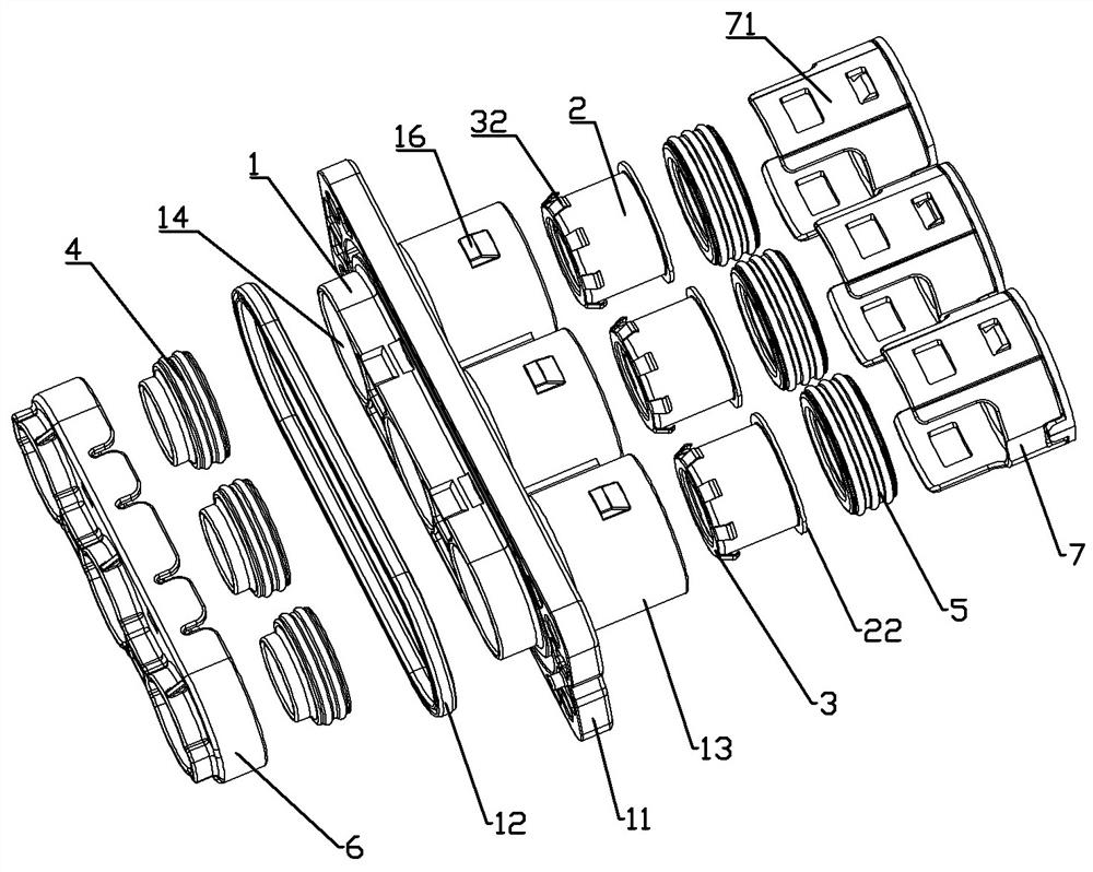
The invention relates to a connector and a shielding cover assembly thereof. The shielding sleeve assembly includes a shielding sleeve extending along the front and rear directions for clamping the outwardly turned shielding layer on the cable insulation skin. The front end of the shielding sleeve is fixedly equipped with a shielding ring, and the shielding ring includes a An annular body assembled on the front end of the shielding sleeve and a plurality of elastic pieces uniformly distributed along the circumference of the annular body and extending toward the rear end of the shielding sleeve to elastically press fit with the metal shell. The shielding ring is fixedly assembled with the shielding sleeve through the annular body. The annular body of the shielding ring is evenly distributed with shrapnel along its circumference. The shrapnel extends to the rear end of the shielding sleeve and elastically presses and fits with the metal shell. The press fit is used to realize the conductive connection with the shielding sleeve, and the axial length of the shielding sleeve assembly is reduced, thereby reducing the axial dimension of the connector.

Description

technical field [0001] The invention relates to a connector and a shielding cover assembly thereof. Background technique [0002] When connecting cables to the inside of the equipment box, a through-hole connector is usually installed on the wall of the box. The perforation is sealed, and in special environments, it is also necessary to use the connector to shield the electric field generated by the cable. [0003] The Chinese invention patent application with the application publication number CN106785591A discloses a shielding sleeve and a connector using the shielding sleeve. The connector includes a connector housing, and the connector housing has a threading hole for threading. The shielding sleeve, the shielding sleeve includes a sleeve body, and the front end of the sleeve body is turned outward and has an elastic arm. The connector also includes a crimping sleeve, the crimping sleeve is matched with the shielding sleeve, and the rear end of the crimping sleeve is p...

Claims


Application Information

Patent Timeline
Patent Type & Authority Patents(China)
IPC IPC(8): H01R13/502H01R13/52H01R13/6588H01R13/6591H01R13/6595
CPCH01R13/502H01R13/5202H01R13/6588H01R13/6591H01R13/6595
Inventor 娄鹏陈建勋郭辉
Owner CHINA AVIATION OPTICAL-ELECTRICAL TECH CO LTD
Why Eureka
Try Eureka