Electric connector combination and electric connector thereof

A technology of electrical connectors and docking connectors, which is applied in the direction of connection and connection device components, circuits, etc., can solve the problem of unfavorable high-frequency signal transmission of electrical connectors, affecting signal shielding effect, and unfavorable signal terminals for high-frequency signal transmission. And other issues

Active Publication Date: 2021-01-22
DEYI PRECISION ELECTRONIC IND CO LTD PANYU
View PDF8 Cites 0 Cited by
  • Summary
  • Abstract
  • Description
  • Claims
  • Application Information

AI Technical Summary

Problems solved by technology

[0003] However, during the transportation or use of the electrical connector, the shield is prone to displacement or vibration, resulting in unstable contact between the abutting pin and the ground terminal, affecting the shielding for the signal. The signal shielding effect of the terminal pair; and there will be dimensional deviations in the electrical connector during the production process, which will cause the abutment pin to fail to contact the ground terminal, which will also affect the shielding effect on the signal The signal shielding effect of the terminal pair is not conducive to the high-frequency signal transmission of the electrical connector
At the same time, the shielding member can only be grounded through a grounding path that is electrically connected to the grounding terminal. Once the grounding path fails, the shielding effect of the shielding member on the signal terminal pair will also be affected. , which is not conducive to the high-frequency signal transmission of the signal terminal pair

Method used


Image

  • Electric connector combination and electric connector thereof
  • Electric connector combination and electric connector thereof
  • Electric connector combination and electric connector thereof

Examples


Embodiment Construction

[0043] In order to facilitate a better understanding of the purpose, structure, features and effects of the present invention, the present invention will now be further described with reference to the accompanying drawings and specific embodiments.

[0044] In order to make it easier to understand the technical solutions of the present invention, in the three-dimensional coordinate axes in the accompanying drawings, the X-axis is defined as the front-rear direction, the Y-axis is defined as the left-right direction, the Z-axis is defined as the up-down direction, and the X-axis, the Y-axis and the Z-axis are defined as the up-down direction. The two are perpendicular to each other.

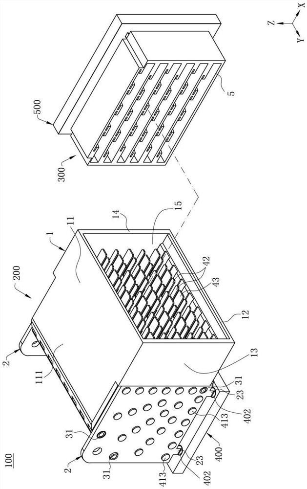
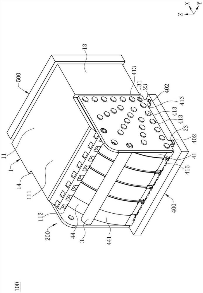
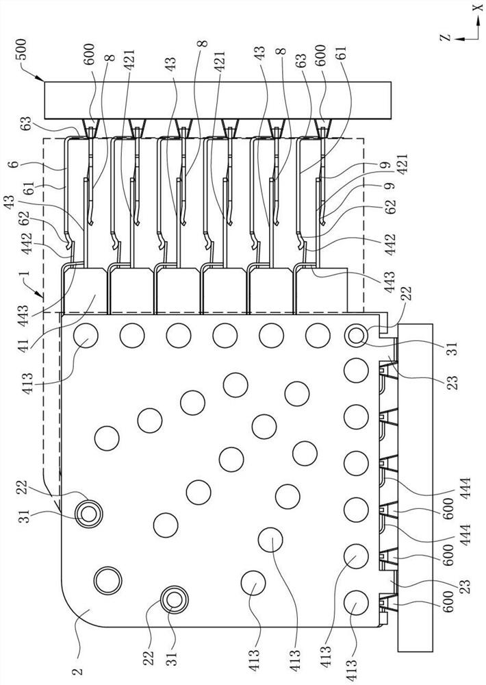
[0045] see Figure 1 to Figure 3 , this is an electrical connector assembly 100 provided by the present invention, comprising an electrical connector 200 and a mating connector 300 docked with the electrical connector 200, defining an up-down direction Z, the electrical connector 200 The lower en...


PUM


Abstract

The invention discloses an electric connector combination and an electric connector thereof. The electric connector combination comprises an electric connector, the electric connector comprises a plurality of first grounding conductors and a plurality of first signal conductor pairs, wherein at least one first shielding piece is provided with a first main body part, the first main body part bendsand extends towards the at least one first grounding conductor to form at least one first grounding part, the first main body part extends forwards to form a first butt joint part, and the first buttjoint part is adjacent to the first grounding part; the electric connector combination further comprises a butt joint connector, which is provided with at least one second shielding piece, the secondshielding piece is provided with a second butt joint part, and when the butt joint connector is inserted into the electric connector and is in electric contact with the first signal conductor pairs, the second butt joint part downwards abuts against the upper surface of the first butt joint part. Therefore, the first grounding part is stably contacted with the upper surface of the first groundingconductor, and the grounding path of the first shielding piece is increased, so that the first shielding piece can effectively shield the first signal conductor pairs.

Description

【Technical field】 [0001] The present invention relates to an electrical connector assembly and its electrical connector, in particular to an electrical connector assembly for transmitting high-frequency signals and its electrical connector. 【Background technique】 [0002] A conventional electrical connector includes an insulating body, a row of conductive terminals is fixed on the insulating body, and a row of the conductive terminals includes a plurality of signal terminal pairs for transmitting high-frequency signals and located in adjacent two The ground terminal between the pair of signal terminals is above the conductive terminal of a shielding member, and the shielding member has a plurality of abutting feet bent and arranged toward the grounding terminal, respectively abutting the plurality of the grounding terminals, so as to pass through the grounding terminal. The contact between the abutting pin and the grounding terminal grounds the shielding member, so as to shi...

Claims


Application Information

Patent Timeline
IPC IPC(8): H01R13/6471H01R13/6581H01R13/502H01R13/02
CPCH01R13/6471H01R13/6581H01R13/02H01R13/502H01R13/514H01R13/6582H01R13/6587H01R13/516
Inventor 蔡伦
Owner DEYI PRECISION ELECTRONIC IND CO LTD PANYU
Why Eureka
Try Eureka