Fluid end

a technology of fluid end and end, which is applied in the direction of positive displacement liquid engine, piston pump, liquid fuel engine, etc., can solve the problems of limiting the pressure rating affecting the economic value affecting the efficiency of the oil and gas production unit, so as to achieve the effect of reducing the risk of rust, and increasing the strength

Inactive Publication Date: 2008-03-11
GD ENERGY PROD LLC
View PDF34 Cites 63 Cited by
  • Summary
  • Abstract
  • Description
  • Claims
  • Application Information

AI Technical Summary

Benefits of technology

[0005]In light of the problems associated with conventional oilfield pumping equipment, it is a principal object of the present invention to provide a fluid end of great strength, durability and fatigue resistance. Such a fluid end features a “mono-block” design wherein its body is produced from a single piece of metal. Passages within the body retain reciprocating plungers and valves that pressurize fluids and control their flow through the fluid end. Since the body does not require seals between its constituent parts, it is not particularly susceptible to internal corrosion, fluid leaks and metal fatigue during normal use.
[0006]It is another object of the invention to provide a fluid end of the type described with reinforced suction valve seat decks. Such seat decks are made possible by employing compact, stem-guided suction valves within the fluid end rather than conventional, and larger, wing-guided valves. The stem-guided valves fit within shallow pockets in the fluid end requiring less material be removed from the fluid end body than was possible in the past. Providing the seat decks with shallow bevels also adds strength by more evenly distributing loads imparted by the suction valves to the remainder to the fluid end body.
[0007]It is an additional object of the invention to provide a fluid end with a body to which a hook, chain, cable, or other like lifting device can be attached so that it can be easily lifted and transported without the use of eyebolts that have a tendency to bend and break. Such a fluid end can, thus, be easily and safely moved about—a great benefit in an oilfield environment where pumps comprising fluid ends rarely remain in place for more than a few months.
[0008]It is a further object of the invention to provide a fluid end featuring hinges for the attachment of a suction manifold thereto. Such hinges permit easy access to the interior of the fluid end for while retaining the manifold in a clean and elevated state for easy repositioning and reattachment. With hinge elements of the sort described, servicing of suction valves within a fluid end can be a one-man job.
[0009]It is an object of the invention to provide improved elements and arrangements thereof in a fluid end for the purposes described which is relatively inexpensive to manufacture and fully dependable in use.

Problems solved by technology

It is difficult to produce oil and gas in an economic manner from low permeability reservoir rocks.
Unfortunately, the joints between the blocks and the supporting features for the valves tend to weaken the body of a fluid end, limiting its pressure rating, and making it susceptible to corrosion, leaks and cracks.
Thus, it is not unusual for the bodies of fluid ends to fail under load, cutting short their useful lives.
Installing and servicing conventional fluid ends is difficult since their parts often weigh hundreds of pounds.
Equally difficult is moving a suction manifold into place beneath a fluid end body since its awkward shape and great weight usually requires numerous hands for proper positioning.

Method used


Image

  • Fluid end
  • Fluid end
  • Fluid end

Examples


Embodiment Construction

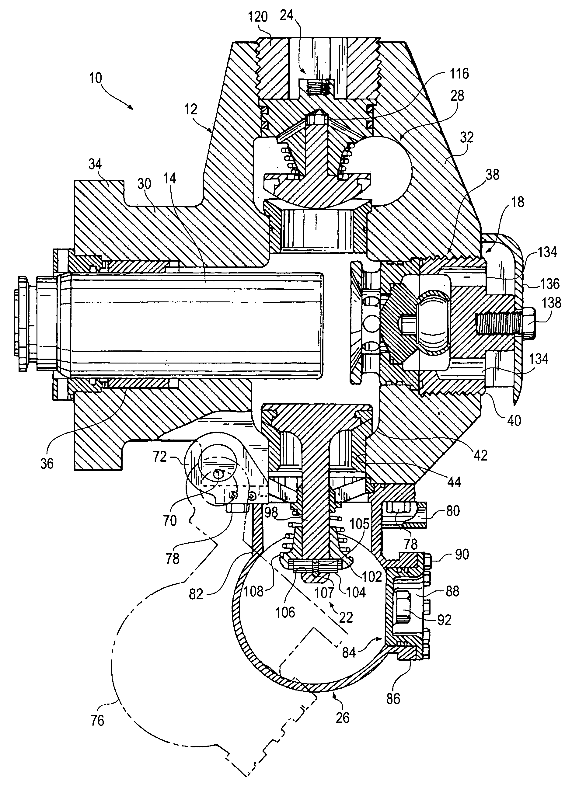
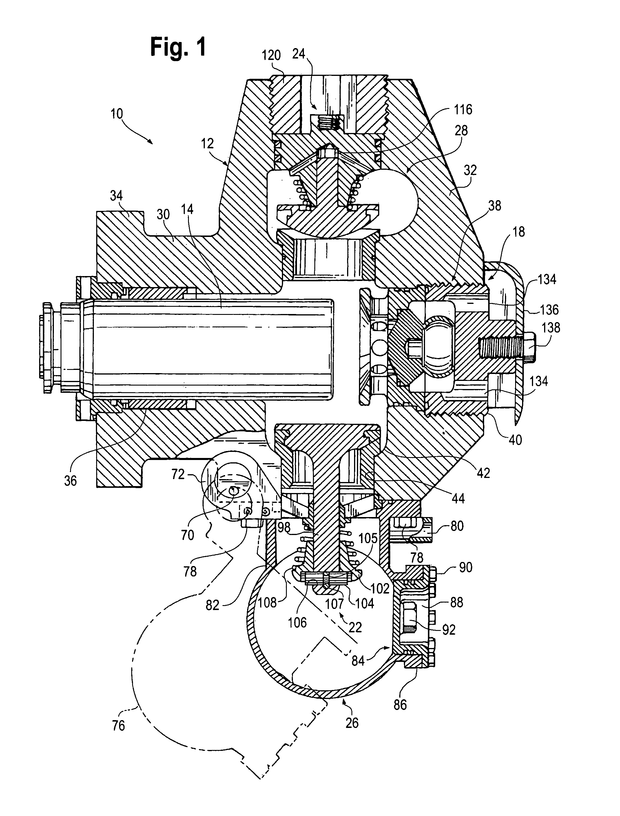
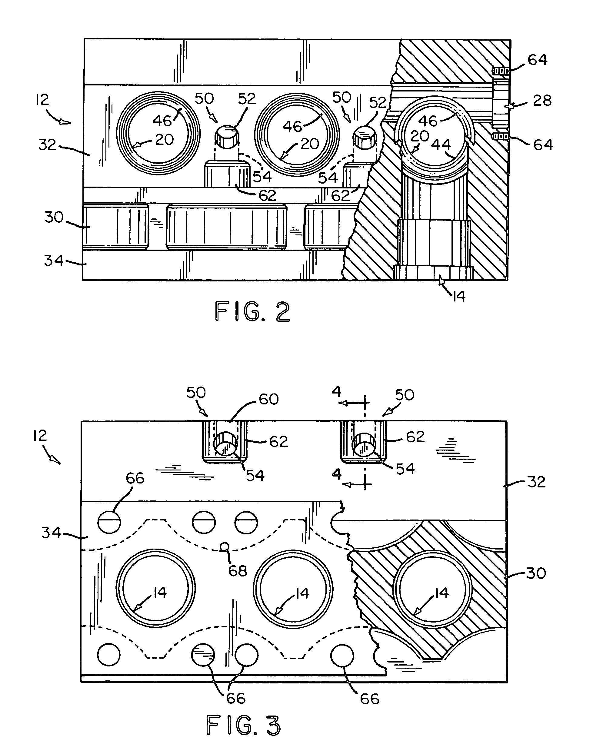
[0018]Referring now to the FIGS., a fluid end in accordance with the present invention is shown at 10. Fluid end 10 includes a body 12 with a plurality of horizontal passages 14 each for receiving a reciprocating plunger 16 at one of its ends and a pressure relief valve 18 at the other of its ends. Body 12 is provided with a corresponding number of vertical passages 20 each of which intersect one of the horizontal passages 14 and contains a suction valve 22 at its bottom and a discharge valve 24 at its top. A suction manifold 26 is hingedly attached to the bottom of body 12 so as to provide a flow of fluid into body 12 via suction valves 22. A discharge passage 28 intersects vertical passages 20 and receives fluid pressurized by plungers 16 via discharge valves 24 and ports such from fluid end 10.

[0019]Body 12 is formed from a high alloy steel forging for maximum strength. Preferably, the forging has a cross-sectional configuration somewhat resembling the letter “H”. The crosspiece ...


PUM


Abstract

A fluid end for a high-pressure pump including a unitary body with a plurality of horizontal passages each for receiving a reciprocating plunger at one of its ends and a pressure relief valve at the other of its ends. The body is provided with a corresponding number of vertical passages each of which intersect one of the horizontal passages and contains a suction valve at its bottom and a discharge valve at its top. A suction manifold is hingedly attached to the bottom of body to provide a flow of fluid into the body via the suction valves. A discharge passage intersects the vertical passages and receives fluid pressurized by the plungers via discharge valves and ports such from the fluid end.

Description

FIELD OF THE INVENTION[0001]The present invention relates generally to pumps having pumping chamber pressure responsive fluid distributors.BACKGROUND OF THE INVENTION[0002]It is difficult to produce oil and gas in an economic manner from low permeability reservoir rocks. Production rates are often boosted by resorting to hydraulic fracturing, a technique that increases rock permeability by opening channels through which hydrocarbons can flow to recovery wells. During hydraulic fracturing, a fluid is pumped into the earth under high pressure where it enters a reservoir rock and fractures it. Proppants are carried in suspension by the fluid into the fractures. When the pressure is released, the fractures partially close on the proppants, leaving channels for oil and gas to flow.[0003]Specialized pumps are used to develop the pressures necessary to complete a hydraulic fracturing procedure or “frac job.” These pumps are usually provided with fluid ends within the body of which reciproc...

Claims


Application Information

Patent Timeline
Patent Type & Authority Patents(United States)
IPC IPC(8): F04B17/00F04B35/00F04B53/00F04B53/16
CPCF04B53/007F04B53/16Y10T137/7838Y10T137/87885
Inventor VICARS, BERTON L.
Owner GD ENERGY PROD LLC
Why Eureka
Try Eureka