Fluid end

a technology of fluid end and pump, which is applied in the direction of pump components, positive displacement liquid engines, liquid fuel engine components, etc., can solve the problems of limiting the pressure rating of the reservoir, affecting the economic production of hydrocarbons, and affecting the use of the reservoir, so as to achieve the effect of ensuring the use and being easy to manufactur

Inactive Publication Date: 2011-08-04
J MAC TOOL
View PDF40 Cites 85 Cited by
  • Summary
  • Abstract
  • Description
  • Claims
  • Application Information

AI Technical Summary

Benefits of technology

[0009]It is an object of the invention to provide improved features and arrangements thereof in a fluid end for the purposes described which is relatively inexpensive to manufacture and fully dependable in use.

Problems solved by technology

It is difficult to economically produce hydrocarbons from low permeability reservoir rocks.
It is the connections between the parts and the supporting features for the valves that tend to weaken a fluid end, limiting its pressure rating, and making it susceptible to cracking under high, cyclical stresses.
Thus, fluid ends sometimes fail prematurely.
The resulting, Y-type fluid ends are costly to make, however.

Method used


Image

  • Fluid end
  • Fluid end
  • Fluid end

Examples


Embodiment Construction

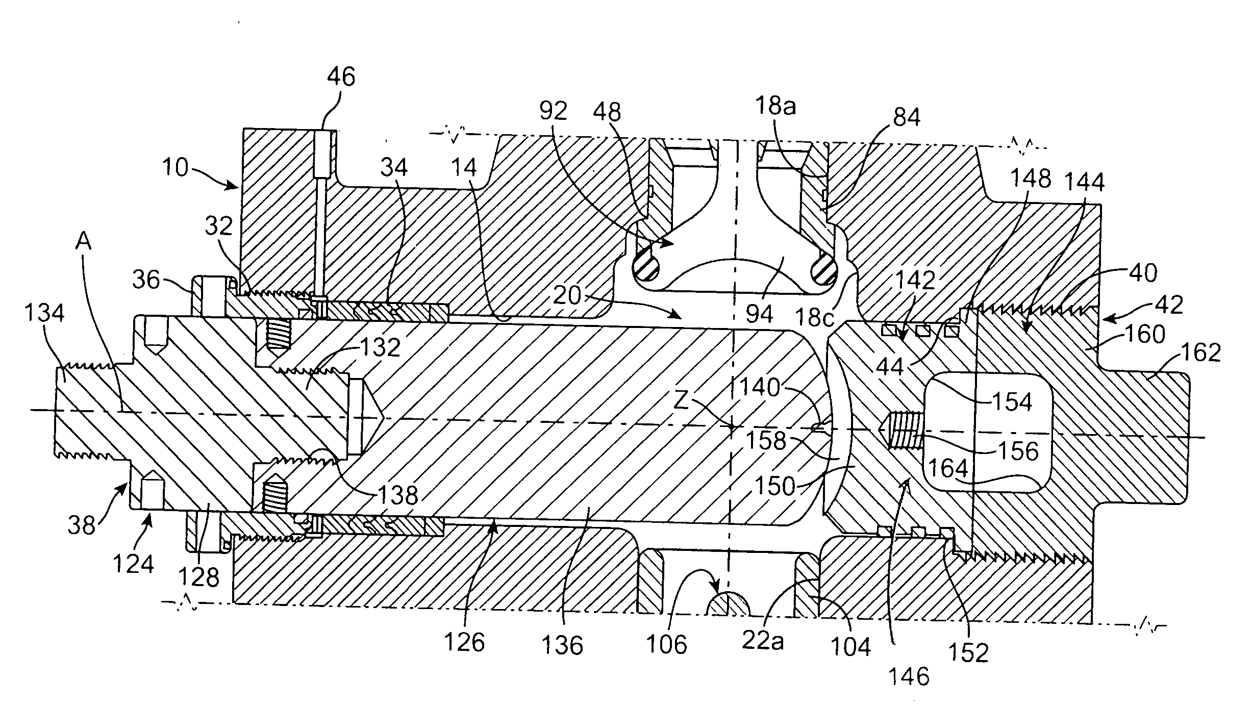
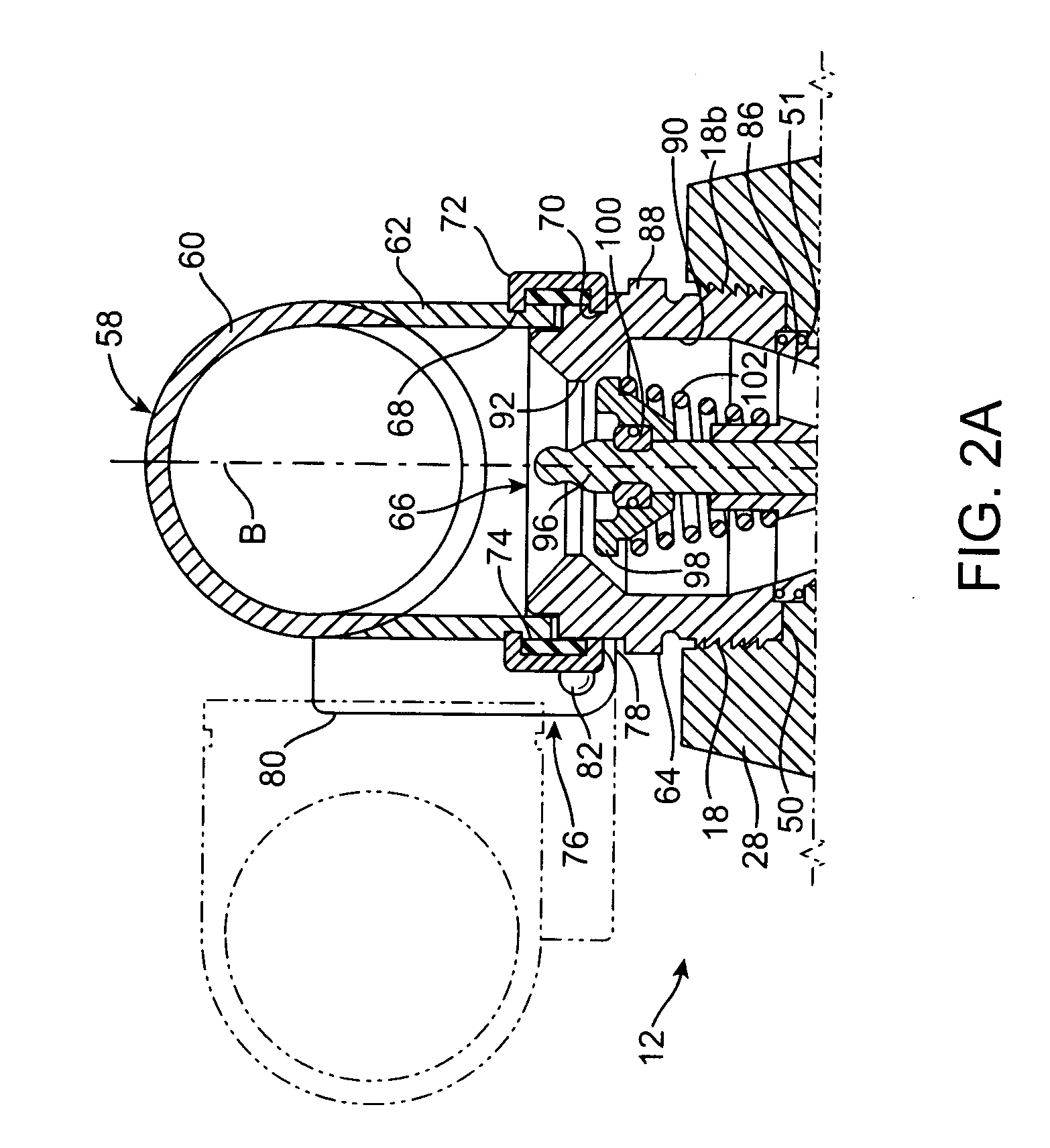
[0017]Referring now to the FIGS., the body 10 of my fluid end 12 is shown. Body 10 has a horizontal, plunger passage 14 that extends from its front to its back. Body 10 also has a horizontal, outlet passage 16 that extends from one of its sides to the other and that is positioned beneath, and oriented at right angles to, plunger passage 14. A suction passage 18 extends vertically downward from the top of body 10 to intersect plunger passage 14 and to define a pumping chamber 20 at the point of intersection. A discharge passage 22 extends vertically downward from pumping chamber 20 to the bottom of body 10 and past outlet passage 16. A horizontal, connector passage 24 places discharge passage 22 and outlet passage 16 in fluid communication with one another.

[0018]Body 10 is a metallic block, a machined forging. To lower its weight and increase its strength, body 10 is provided with a plunger section 26 of reduced height that contains the outer end of plunger passage 14 and is adapted ...


PUM


Abstract

A fluid end for a high-pressure pump including a metallic block having a front, back, top, bottom, and opposed sides. The block has a horizontal, plunger passage extending from the front to the back thereof. A horizontal, outlet passage extends from one of the opposed sides of the block to the other with the outlet passage being positioned beneath, and at right angles to, the plunger passage. A suction passage extends vertically downward from the top of the block and intersects the plunger passage to define a pumping chamber at the point of intersection. A discharge passage extends vertically downward from the pumping chamber to the bottom of the block. The discharge passage is located adjacent to the outlet passage. A connector passage extends from the discharge passage to the outlet passage so as to place the discharge passage and outlet passage in fluid communication. A reciprocating plunger assembly is located the end of the plunger passage adjacent the back of the block. A plug is located in the end of the plunger passage adjacent the front of the block. A suction valve is located in the suction passage. A discharge valve is located in the discharge passage. A fluid supply manifold is pivotally secured to the top of the block and is in fluid communication with the suction passage.

Description

FIELD OF THE INVENTION[0001]The present invention relates generally to pumps having pumping chamber pressure responsive fluid distributors.BACKGROUND OF THE INVENTION[0002]It is difficult to economically produce hydrocarbons from low permeability reservoir rocks. Oil and gas production rates are often boosted by hydraulic fracturing, a technique that increases rock permeability by opening channels through which hydrocarbons can flow to recovery wells. During hydraulic fracturing, a fluid is pumped into a reservoir rock under high pressure where it cracks or fractures the rock. Proppants are carried in suspension by the pumped fluid into the fractures. When the pressure is released, the fractures close on the proppants leaving open channels for hydrocarbons to flow.[0003]Specialized pumps are used to deliver fracture fluids at sufficiently high rates and pressures to complete a hydraulic fracturing procedure or “frac job.” These pumps are usually provided with fluid ends having both ...

Claims


Application Information

Patent Timeline
Patent Type & Authority Applications(United States)
IPC IPC(8): F04B53/10F04B53/00
CPCF04B53/10F04B53/00F04B53/16F04B53/22F04B53/007
Inventor VICARS, BERTON L.
Owner J MAC TOOL
Why Eureka
Try Eureka