Method and system for manufacturing a coupler knuckle

a manufacturing method and coupler technology, applied in the field of railcars, can solve the problems of many knuckles failing from internal and/or external inconsistencies, labor-intensive coupler knuckles, and train delays, and achieve the effect of reducing or eliminating at least some of the disadvantages and problems

Active Publication Date: 2007-12-04
MCCONWAY & TORLEY LLC
View PDF8 Cites 63 Cited by
  • Summary
  • Abstract
  • Description
  • Claims
  • Application Information

AI Technical Summary

Benefits of technology

[0005]The present invention provides a method and system for manufacturing a coupler knuckle that substantially eliminates or reduces at least some of the disadvantages and problems associated with previous methods and systems.
[0010]Technical advantages of particular embodiments include a system and method for manufacturing a coupler knuckle using fewer than three cores for forming internal cavities within the knuckle. For example, a single core may be used to form kidney, finger and pivot pin cavities within the knuckle. Accordingly, a stronger and more efficient knuckle is manufactured because there are fewer cores to move during casting. In addition, less materials are required to manufacture the coupler knuckle since nails and / or chaplets will not be needed to hold in place three separate cores in the cope and drag mold sections. Moreover, the manufacturing process for the knuckle may take less time and labor since fewer cores need to be positioned within a mold cavity for casting.

Problems solved by technology

The repair of a failed coupler knuckle can be labor intensive, can sometimes take place in very inclement weather and can cause train delays.
Many knuckles fail from internal and / or external inconsistencies in the metal through the knuckle.
If one or more cores move during the casting process, then some knuckle walls may end up thinner than others resulting in offset loading and increased failure risk during use of the knuckle.

Method used


Image

  • Method and system for manufacturing a coupler knuckle
  • Method and system for manufacturing a coupler knuckle
  • Method and system for manufacturing a coupler knuckle

Examples


Embodiment Construction

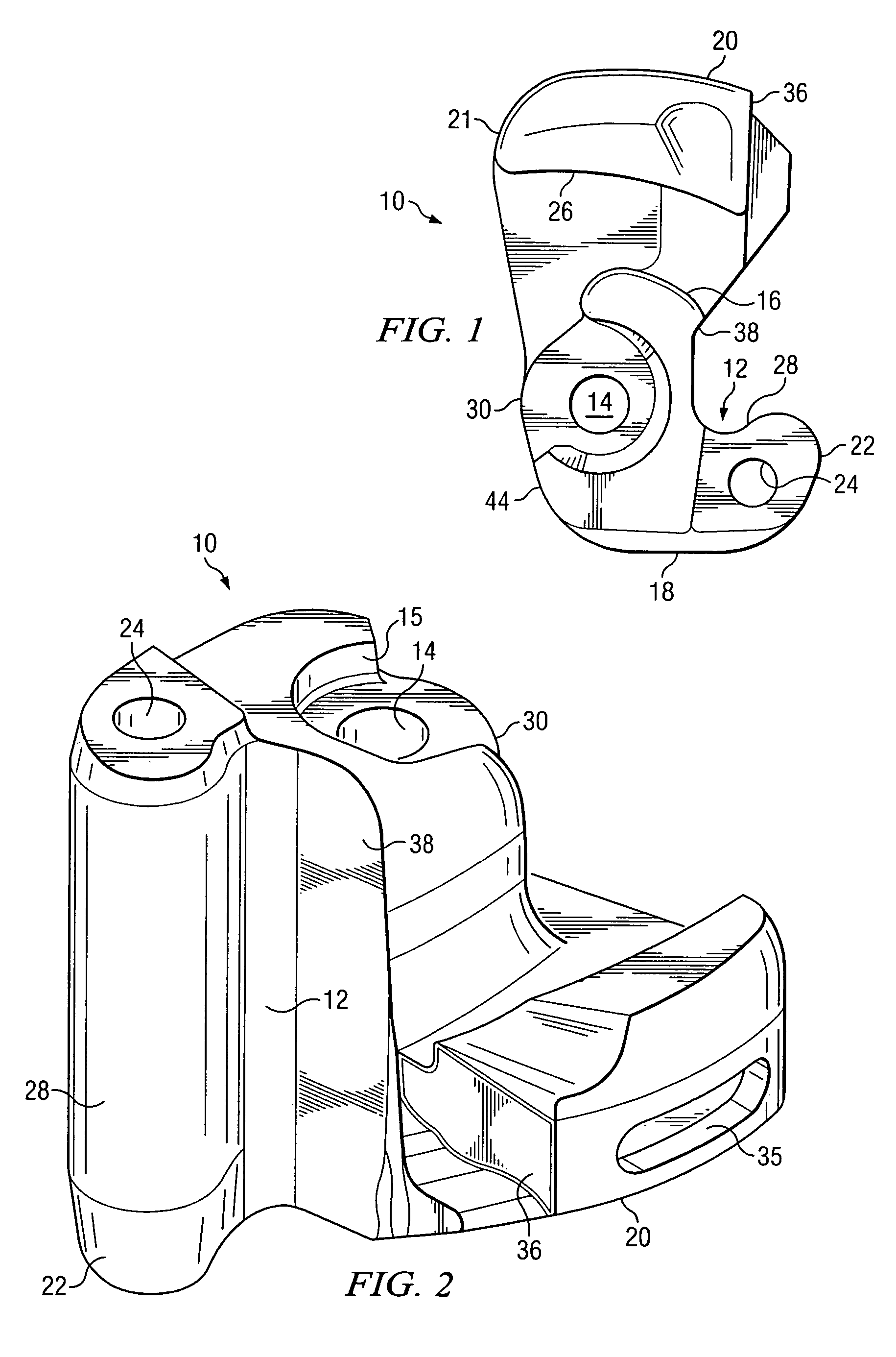
[0023]FIG. 1 is a top view of an example coupler knuckle 10 in accordance with a particular embodiment. Coupler knuckle 10 includes a tail section 20, a hub section 30 and a front face section 18. Hub section 30 includes a pivot pin hole 14 formed therein for receiving a pivot pin to pivotally couple the knuckle 10 to a coupler for coupling to a railcar. Pivot pin hole 14 may have generally cylindrical sidewalls and may have a middle region lacking sidewalls. Coupler knuckle 10 also includes a buffing shoulder 16, a tail stop 21, a pulling lug 26, a lock wall 36, a throat 38 and a heel 44.

[0024]Front face section 18 includes a nose section 22, which includes a generally cylindrical flag opening 24 formed in an end region of the nose section 22. A pulling face portion 28 is disposed inwardly from nose section 22. At least a portion of the pulling face portion 28 includes a bearing surface area 12 which bears against a similar surface of a coupler knuckle of an adjacent railcar to cou...


PUM

PropertyMeasurementUnit
perimeteraaaaaaaaaa
areaaaaaaaaaaa
lengthaaaaaaaaaa

Abstract

A method for manufacturing a railcar coupler knuckle includes providing a cope mold portion and a drag mold portion. The cope and drag mold portions have internal walls defining at least in part perimeter boundaries of a coupler knuckle mold cavity. The method includes positioning one or two internal cores within either the cope mold portion or the drag mold portion. The one or two internal cores are configured to define a kidney cavity, a finger cavity and a pivot pin cavity of a coupler knuckle. The method includes closing the cope and drag mold portions with the one or two internal cores therebetween and at least partially filling the mold cavity with a molten alloy, the molten alloy solidifying after filling to form the coupler knuckle.

Description

TECHNICAL FIELD OF THE INVENTION[0001]This invention relates in general to railcars and, more particularly, to a method and system for manufacturing a coupler knuckle.BACKGROUND OF THE INVENTION[0002]Railcar couplers are disposed at each end of a railway car to enable joining one end of such railway car to an adjacently disposed end of another railway car. The engageable portions of each of these couplers is known in the railway art as a knuckle. For example, railway freight car coupler knuckles are taught in U.S. Pat. Nos. 4,024,958; 4,206,849; 4,605,133; and 5,582,307.[0003]Knuckle failure accounts for about 100,000 train separations a year, or about 275 separations per day. Most of these separations occur when the train is out of a maintenance area. In such cases, a replacement knuckle, which can weigh about 80 pounds, must be carried from the locomotive at least some of the length of the train, which may be up to 25, 50 or even 100 railroad cars in length. The repair of a failed...

Claims


Application Information

Patent Timeline
Patent Type & Authority Patents(United States)
IPC IPC(8): B22D33/04
CPCB22C9/02B22C9/103B22D17/24B61G3/04B22C9/22Y10T29/49988B22C9/108B61G3/10
Inventor MAUTINO, P. SCOTTGAGLIARDINO, JOSEPH L.MAXEINER, MICHAEL D.
Owner MCCONWAY & TORLEY LLC
Why Eureka
Try Eureka