Rooftop photovoltaic module

a photovoltaic module and roof top technology, applied in the direction of heat collector mounting/support, light radiation electric generator, lighting and heating apparatus, etc., can solve the problems of increasing the likelihood of water leakage through the roof top system, significant associated installation labor, etc., to reduce the build-up of hot air, simple, low cost, and the effect of simpl

Inactive Publication Date: 2006-10-12
SHARP MFG COMPANY OF AMERICA A DIV OF SHARP ELECTRONICS
View PDF5 Cites 63 Cited by
  • Summary
  • Abstract
  • Description
  • Claims
  • Application Information

AI Technical Summary

Benefits of technology

[0014] Still yet another object of the invention is to provide a simple, low cost method of restraining the front edge of a row of photovoltaic modules integrated into a concrete tile roof.
[0015] Another object of the invention is to provide a simple, low cost method of restraining electrical cables in a building-integrated photovoltaic module and system.
[0016] Another object of the invention is to provide means for reducing the build-up of hot air underneath a building-integrated photovoltaic module and system.

Problems solved by technology

The current technology uses screws in the side of a module frame for electrical grounding, with significant associated installation labor.
Current modules are not generally designed to adapt to multiple sizes of concrete tiles.
These modules are many times designed to screw or nail directly into the house roof, which increases the likelihood of water leakage through the roofing system.
This lack of integrity in the PV array system also results in a requirement for roof tile PV modules that are deeper (ridge-to-soffit) than absolutely necessary in order to form an overlap between modules in an attempt to remedy the deficiency in their water resistance capabilities, with accompanying higher material costs.
The additional installation pieces required for mounting also increases the labor time required for installation.

Method used


Image

  • Rooftop photovoltaic module
  • Rooftop photovoltaic module
  • Rooftop photovoltaic module

Examples


Embodiment Construction

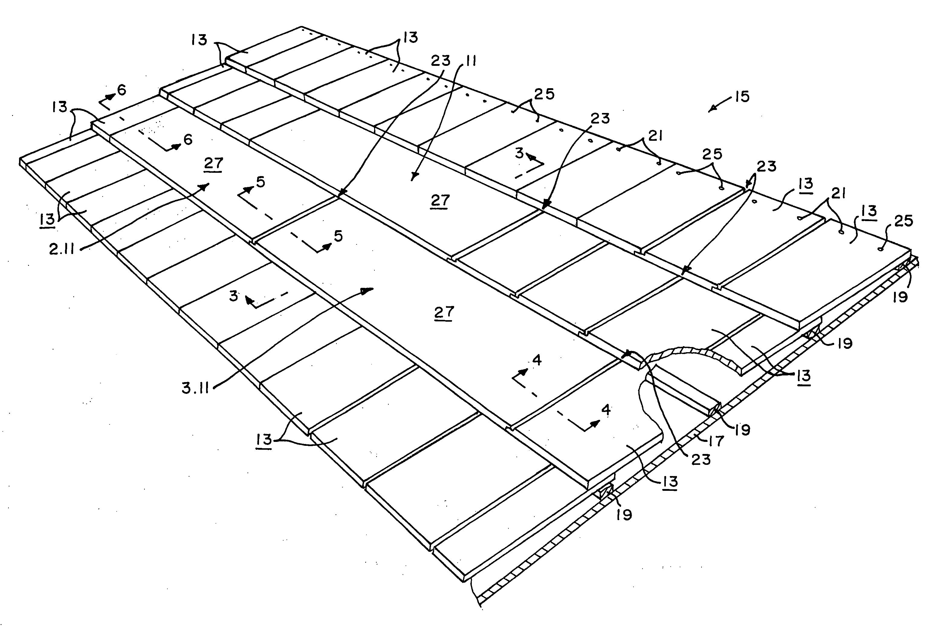
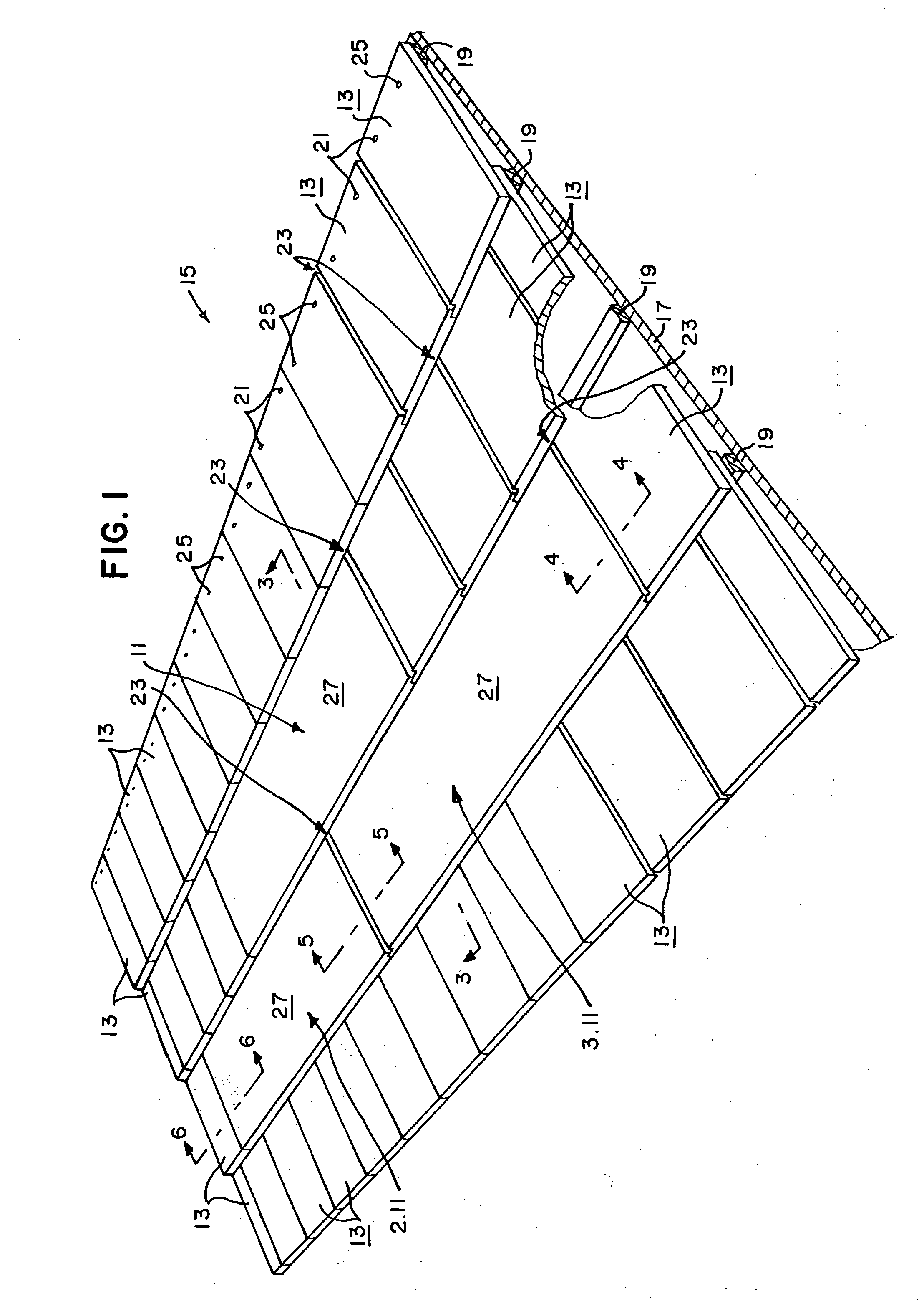
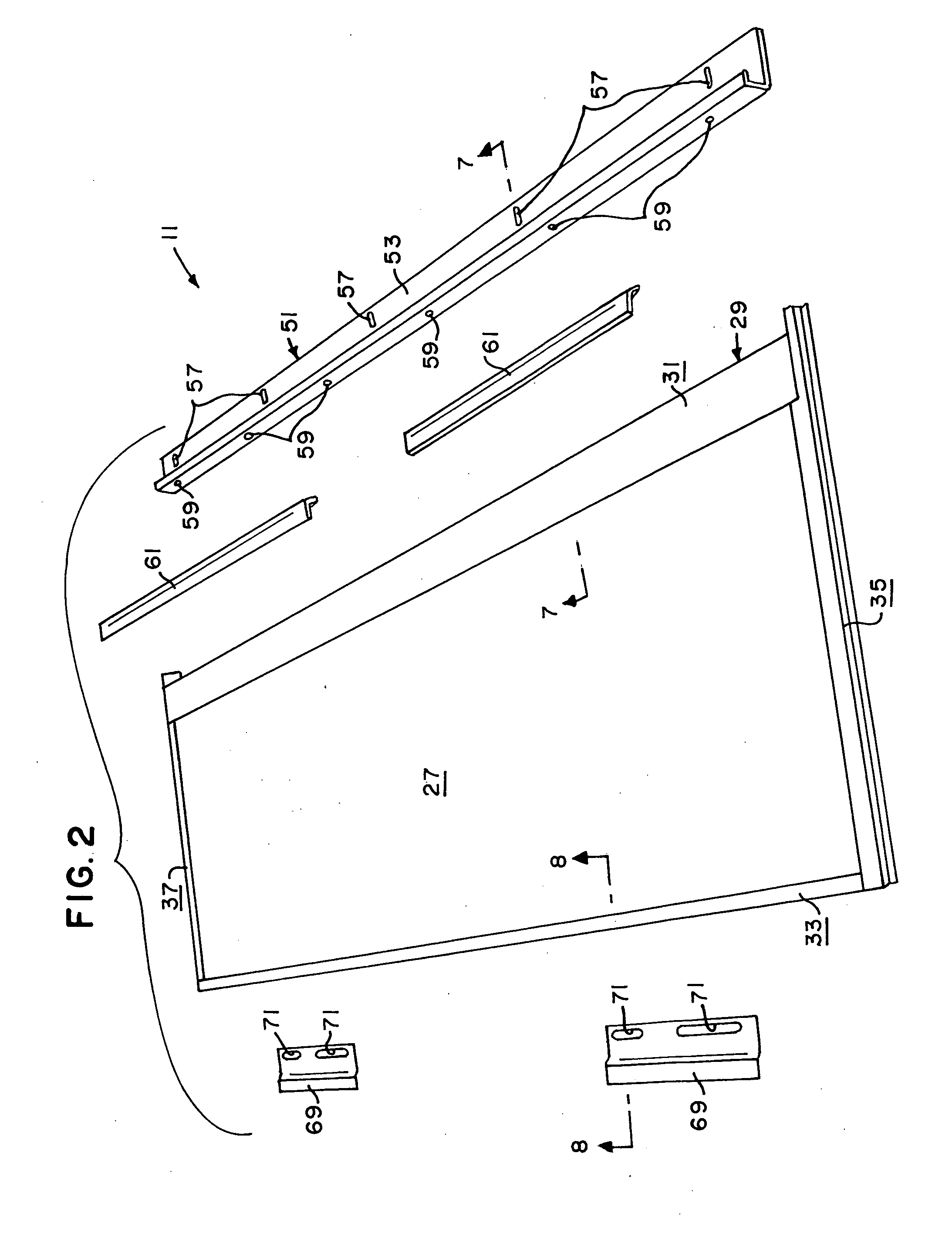
[0029] A preferred embodiment of the photovoltaic module of the present invention is shown in the drawings and identified by the numeral 11. The photovoltaic module 11 is designed for integrated and interconnected use with a plurality of like photovoltaic modules (e.g., a second photovoltaic module 2.11, and a third photovoltaic module 3.11 as shown in FIG. 1), and a plurality of roof tiles (e.g., concrete roof tiles 13 as shown in FIG. 1) on a roof 15. The roof 15 includes a roof deck 17 and a plurality of battens 19 which extend generally horizontally across the roof deck 17 for allowing the roof tiles 13 to be attached to and installed on the roof deck 17 in any typical manner as will now be apparent to those skilled in the art. For example, each roof tile 13 may have a pair of spaced apart apertures 21 adjacent the top edge thereof through which screws, nails or the like (not shown) can be used to secure the roof tile 13 to a batten 19, and thus to the roof 15. FIG. 1 shows the ...


PUM


Abstract

A photovoltaic module for installation with roof tiles on a sloping roof. The photovoltaic module includes a photovoltaic panel; a frame surrounding the panel; and attachment structure for allowing the panel and the frame to be attached to a sloping roof in an interlocking and overlapping fashion with roof tiles while allowing adjustment of the location of the panel and the frame along the slope of the sloping roof.

Description

CROSS REFERENCE TO RELATED APPLICATIONS [0001] This application is a non-provisional application claiming priority of pending U.S. provisional application 60 / 669,659, filed Apr. 8, 2005, entitled “PHOTOVOLTAIC SYSTEM OF INTERLOCKING ROOFTOP MODULES,” fully incorporated herein by reference.BACKGROUND OF THE INVENTION [0002] 1. Field of the Invention [0003] This invention relates generally to the field of photovoltaic generation of electricity and more specifically to a photovoltaic module and a system of interlocking rooftop photovoltaic modules. [0004] 2. Background Art [0005] Solar photovoltaic (PV) systems convert energy from the sun's radiation directly into electricity for a multitude of end uses. One common application of PV systems is installation on the roofs of residences, where electricity generated as direct current is inverted to alternating current and used to displace utility grid-generated electricity for house electrical loads, such as heating and light. In houses tha...

Claims


Application Information

Patent Timeline
Patent Type & Authority Applications(United States)
IPC IPC(8): H02N6/00
CPCE04D2001/3458F24J2/045F24J2/5211F24J2/5262F24J2/5264H02S20/23F24J2002/0061Y02B10/12Y02B10/20Y02E10/47F24J2002/0053E04D1/29E04D1/2916E04D1/2918F24S20/67F24S25/20F24S25/67F24S25/70F24S2020/12F24S2020/13Y02B10/10Y02E10/50
Inventor JOHNSON, BERTRAND LEROY IIIBOSWELL, KENNETH RICHARDUMEMOTO, AKIMASA
Owner SHARP MFG COMPANY OF AMERICA A DIV OF SHARP ELECTRONICS
Why Eureka
Try Eureka