a light emitter

An optical transmitter and modulator technology, applied in the field of optoelectronic communication, can solve the problems of increasing the circuit area of ​​the optical transmitter, high DC power consumption and high circuit complexity of the optical transmitter, unfavorable high-density multi-channel integrated design, etc.

Active Publication Date: 2021-03-26
SHANGHAI JIAO TONG UNIV
View PDF3 Cites 0 Cited by
  • Summary
  • Abstract
  • Description
  • Claims
  • Application Information

AI Technical Summary

Problems solved by technology

[0006] The object of the present invention is to provide an optical transmitter to solve the problems of high DC power consumption, high circuit complexity, and increased occupied area of ​​the optical transmitter circuit in the prior art, which is not conducive to Problems in the integrated design of high-density multi-channel

Method used


Image

  • a light emitter
  • a light emitter
  • a light emitter

Examples


Embodiment Construction

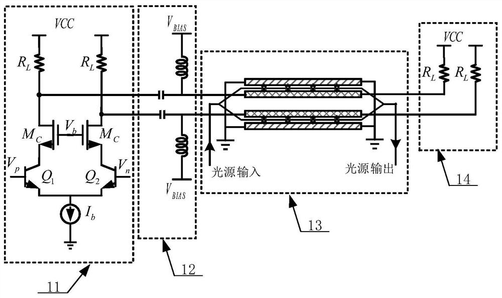
[0057] As mentioned in the background, the high DC power consumption, high circuit complexity, and increased area occupied by the optical transmitter circuit in the prior art are not conducive to high-density multi-channel integrated design. The study found that for the optical transmitter using AC coupling, the specific as figure 1 As shown, it includes: a current mode logic driving module 11, a DC bias module 12, a Mach-Zehnder modulator 13 and a termination module 14, the current mode logic driving module 11 communicates with the Mach through the DC bias module 12 -Zehnder modulator 13 connection, that is, the current mode logic drive module 11 is connected to the Mach-Zehnder modulator in an AC coupling manner, and the Mach-Zehnder modulator 13 is connected to the termination module 14 , the current mode logic drive module 11 is used to provide a high-speed differential drive signal; the DC bias module 12 is used to provide a bias voltage to the Mach-Zehnder modulator 13; ...


PUM


Abstract

The invention discloses a light emitter, which comprises a current mode logic driving module, a modulator and a terminating module, the current mode logic driving module is connected with the input end of the modulator in a direct coupling mode, and the current mode logic driving module is used for generating and outputting a high-speed differential driving signal; the output end of the modulatoris connected with the input end of the terminating module in a direct coupling mode; the modulator is used for modulating an optical signal of the modulator according to the received high-speed differential driving signal to obtain a modulated optical signal and outputting the modulated optical signal; and the terminating module is used for performing far-end impedance matching on the received high-speed differential driving signal. The light emitter has the advantages of saving hardware cost, reducing direct current power consumption, reducing circuit design complexity and facilitating high-density multi-channel integrated design.

Description

technical field [0001] The invention relates to the technical field of photoelectric communication, in particular to an optical transmitter. Background technique [0002] As the bandwidth requirements of data communication are getting higher and higher, silicon-based optical interconnection has become an effective way to replace electrical interconnection as short-distance high-speed and high-bandwidth data transmission because of its high bandwidth, low transmission loss, and compatibility with electrical chips. An optical transmission link may generally include an optical transmitter, an optical receiver, and an optical transmission medium. Among them, the optical transmitter converts electrical signals into optical signals, and the required components mainly include light sources, drivers and electro-optic modulators. [0003] According to different modulation methods, it can be divided into direct modulation and external modulation. Mach-Zehnder Modulator (MZM) is a wi...

Claims


Application Information

Patent Timeline
Patent Type & Authority Patents(China)
IPC IPC(8): H04B10/50H04B10/54
CPCH04B10/501H04B10/505H04B10/54
Inventor 纪鹏飞宗诚何卫锋刘永超林文淼毛志刚
Owner SHANGHAI JIAO TONG UNIV
Why Eureka
Try Eureka