Mattress assembly and method
A technology of mattresses and components, applied to mattresses, spring mattresses, bed frames, etc., can solve problems such as increasing costs
Active Publication Date: 2019-09-20
BEDGEAR
16 Cites 0 Cited by
AI-Extracted Technical Summary
Problems solved by technology
Therefore, shipping the mattress as freight adds t...
Abstract
A mattress assembly includes a chassis having top and bottom walls and first and second sidewalls that each extend from the top wall to the bottom wall. Inner surfaces of the walls and the sidewalls define an interior cavity. The top and bottom walls each include a first section that is connected to the first sidewall and a second section that is connected to the second sidewall such that the first sections are pivotable relative to the first sidewall and the second sections are pivotable relative to the second sidewall. The first section of the top wall is pivotable relative to the second section of the top wall and the first section of the bottom wall is pivotable relative to the second section of the bottom wall. A spring assembly is configured to be positioned within the interior cavity.
Application Domain
Stuffed mattressesSpring mattresses +1
Technology Topic
EngineeringMechanics +1
Image
Examples
- Experimental program(1)
Example Embodiment
[0040] The present disclosure can be understood more easily by referring to the following detailed description of the present disclosure in conjunction with the accompanying drawings, which form a part of the present disclosure. It should be understood that the present disclosure is not limited to the specific devices, conditions or parameters described and/or shown herein, and the terms used herein are only for the purpose of describing specific embodiments by way of example, and are not intended to limit the claimed disclosure .
[0041] In addition, as used in the specification and including the appended claims, unless the context clearly dictates otherwise, the singular forms "a", "an" and "the" include the plural and refer to specific values The reference includes at least that specific value. Ranges may be expressed herein as from "about" or "approximately" one particular value and/or to "about" or "approximately" another particular value. When such a range is expressed, another embodiment includes from one specific value and/or to another specific value. Similarly, when a value is expressed as an approximation by using the prefix "about", it will be understood that the particular value forms another embodiment. It should also be understood that all spatial references, such as horizontal, vertical, top, upper, lower, bottom, left and right sides, are for illustration purposes only, and can be varied within the scope of the present disclosure. For example, the references "upper" and "lower" are relative and only used in the context of another, and are not necessarily "superior" and "lower".
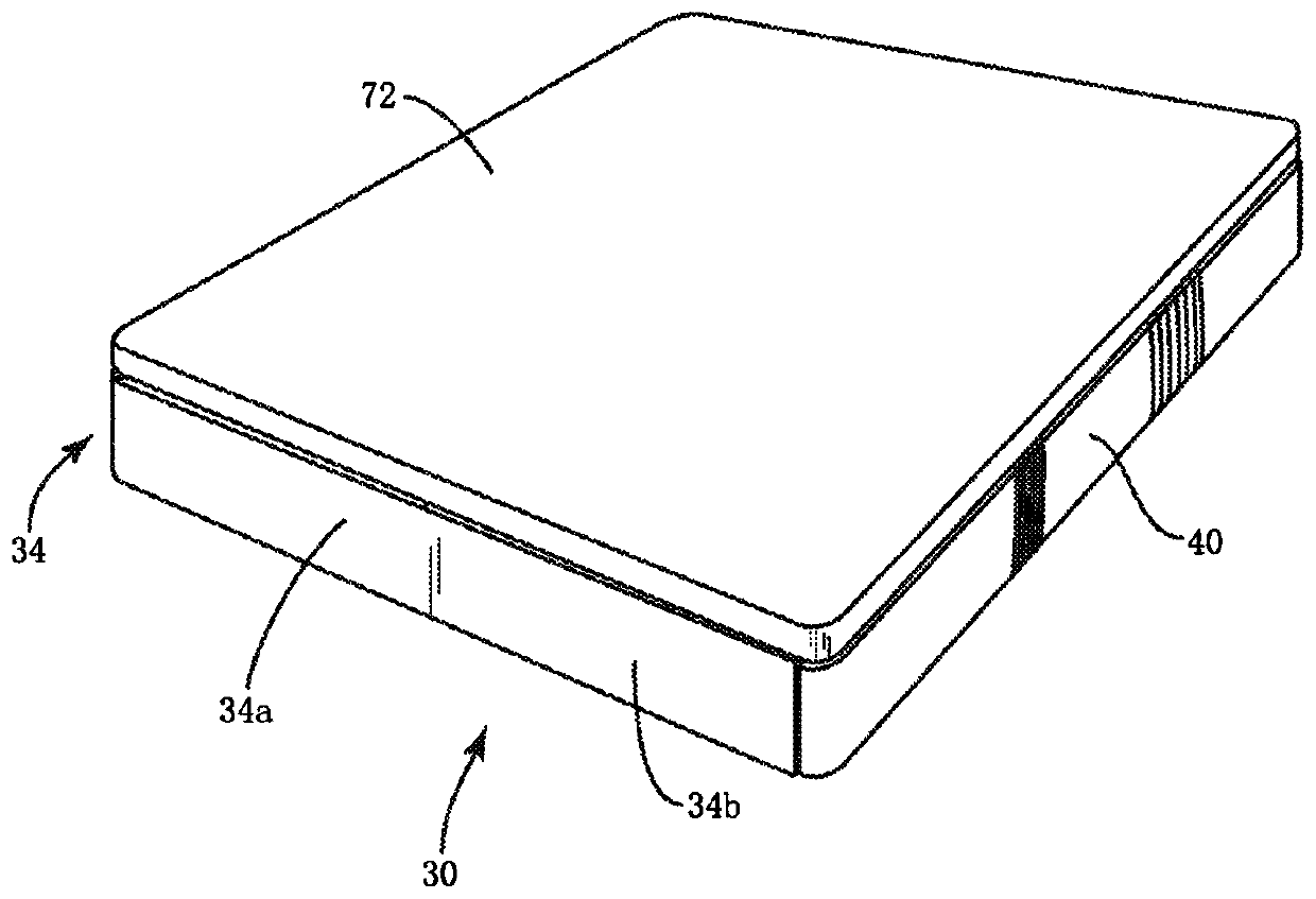
[0042] The following discussion includes a description of a mattress top pad according to the principles of the present disclosure. Alternative embodiments are also disclosed. Reference will now be made in detail to exemplary embodiments of the present disclosure, which are shown in the accompanying drawings. Go to Figure 1-26 , Shows the components of the air booster cushion, such as the mattress assembly 30.
[0043] The mattress assembly 30 is configured to be located above the box spring. In some embodiments, the mattress assembly 30 is configured to cover all or a portion of the top surface of the box spring. In some embodiments, the mattress assembly 30 is configured to be larger than the top surface of the box spring. In some embodiments, the mattress assembly 30 has substantially the same size and shape as the top surface of the box spring. In some embodiments, the mattress assembly 30 is a standard size mattress, such as a twin mattress, a full mattress, a queen mattress, or a king mattress. Or California king mattress (California king mattress). In some embodiments, the mattress assembly 30 is a crib mattress.
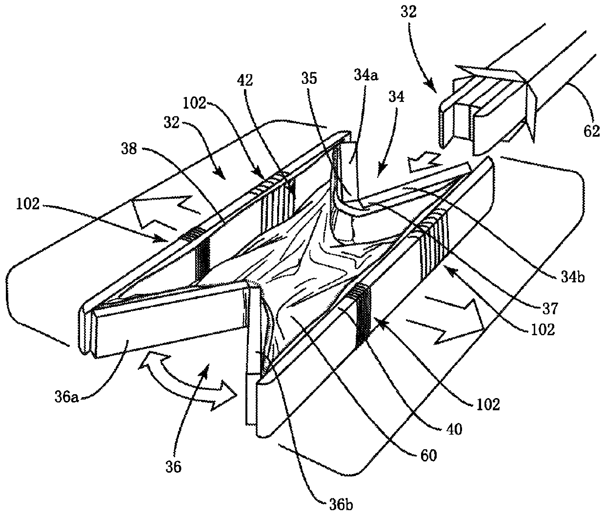
[0044] The mattress assembly 30 includes a bottom frame 32 including a top wall 34 and a bottom wall 36 positioned opposite to the top wall 34. The base frame 32 includes a first side wall 38 and a second side wall 40 positioned opposite to the first side wall 38. The side walls 38, 40 each extend from the top wall 34 to the bottom wall 36. The inner surfaces of the top wall 34 and the bottom wall 36 and the side walls 38, 40 define an inner cavity 42 configured to house the roller blind and one or more spring sets, as discussed herein. In some embodiments, the base frame is made of a rigid material, such as PVC, to provide the base frame 32 with strength and rigidity.
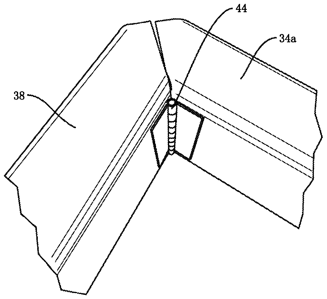
[0045] The top wall 34 includes a first portion 34 a connected to the side wall 38 and a second portion 34 b connected to the side wall 40. Part 34a passes through a mechanical bearing (e.g. hinge 44 ( image 3 with 3A )) Connect to the side wall 38 to allow the portion 34a to pivot relative to the side wall 38. The hinge 44 connecting the part 34a to the side wall 38 is configured to move the part 34a between a first orientation and a second orientation. In the first orientation, the part 34a extends at an acute angle relative to the side wall 38 and in the second orientation Among them, the portion 34a extends perpendicularly with respect to the side wall 38. The portion 34b is connected to the side wall 40 by a hinge 44 to allow the portion 34b to pivot relative to the side wall 40. The hinge 44 connecting the portion 34b to the side wall 40 is configured to move the portion 34b between a first orientation and a second orientation. In the first orientation, the portion 34b extends at an acute angle relative to the side wall 40 and in the second orientation Among them, the portion 34b extends vertically with respect to the side wall 40. The bottom wall 36 includes a first portion 36 a connected to the side wall 38 and a second portion 36 b connected to the side wall 40. The portion 36 a is connected to the side wall 38 by a hinge 44 to allow the portion 36 b to pivot relative to the side wall 38. The hinge 44 connecting the part 36a to the side wall 38 is configured to move the part 36a between a first orientation and a second orientation. In the first orientation, the part 36a extends at an acute angle relative to the side wall 38 and in the second orientation Here, the portion 36a extends perpendicularly with respect to the side wall 38. The portion 36b is connected to the side wall 40 by a hinge 44 to allow the portion 36b to pivot relative to the side wall 40. The hinge 44 connecting the portion 36b to the side wall 40 is configured to move the portion 36b between a first orientation and a second orientation. In the first orientation, the portion 36b extends at an acute angle relative to the side wall 40 and in the second orientation Among them, the portion 36b extends perpendicularly to the side wall 40.
[0046] In some embodiments, the hinge 44 is connected to the inner surfaces of the walls 34, 36 and the side walls 38, 40, such as image 3 Shown. For example, the first part of the hinge 44 connecting the part 34a of the wall 34 to the side wall 38 is fixed to the inner surface of the side wall 38, and the second part of the hinge 44 connecting the part 34a of the wall 34 to the side wall 38 is fixed to the top wall The inner surface of 34, such as Figure 7 Shown. As understood by those of ordinary skill in the art, the hinge 44 connecting the portions 34b, 36a, and 36b to the side walls 38, 40 can be similarly positioned. In some embodiments, the chassis 32 is integral, and the hinge 44 is a living hinge. In such an embodiment, the junctions between the walls 34, 36 and the side walls 38, 40 have a reduced thickness to allow the walls 34, 36 to pivot relative to the side walls 38, 40. In some embodiments, at least one of the hinges 44 may include a barrel hinge, a pivot hinge, a mortise hinge, a watch case hinge, a piano hinge, a hidden hinge, a butterfly hinge, a flag hinge, a strap hinge, and H Type hinge, HL type hinge, back hinge hinge, flush hinge, flat head hinge (coach hinge), lift hinge, double-action spring hinge, T-shaped hinge, friction hinge, safety hinge, crank hinge, lifting hinge or self-closing hinge. In some embodiments, at least one of the hinges 44 may include a hinge embedded in at least one of the walls 34, 36 and the side walls 38, 40. In some embodiments, at least one of the hinges 44 may include a belt buckle and release. In such an embodiment, the hinge 44 includes a male buckle end that snaps into the female buckle end.
[0047] In some embodiments, such as Figure 3A As shown, one or more of the hinges 44 may include a portion 106 and a portion 108. In some embodiments, the portion 106 is connected to the side wall 38 and the portion 108 is connected to the portion 34 a of the wall 34. In some embodiments, portion 106 is connected to side wall 40 and portion 108 is connected to portion 34b of wall 34. In some embodiments, the portion 106 is connected to the side wall 38 and the portion 108 is connected to the portion 36 a of the wall 36. In some embodiments, the portion 106 is connected to the side wall 40 and the portion 108 is connected to the portion 36b of the wall 36. In some embodiments, part 106 is directly connected to part 108. In some embodiments, hinge 44 includes one or more portions 110 located between portion 106 and portion 108. The pin 112 extends through the portions 106 and 110 to allow the portion 106 to pivot relative to the portion 110. Likewise, the pin 112 extends through the portions 108 and 110 to allow the portion 108 to pivot relative to the portion 110. In embodiments that include multiple portions 110, the pin 112 also extends through adjacent portions 110 to allow the adjacent portions 110 to pivot relative to each other. In some embodiments, when the portion 106 pivots relative to the portion 110, a portion of the portion 106 rotates within the cavity in the portion 110 and/or a portion of the portion 110 rotates within the cavity in the portion 106. In some embodiments, when the portion 108 is pivoted relative to the portion 110, a portion of the portion 108 rotates within the cavity in the portion 110 and/or a portion of the portion 110 rotates within the cavity in the portion 108. In some embodiments, when one of the parts 110 pivots relative to the other of the parts 110, a part of one of the parts 110 rotates within the cavity of the other of the parts 110.
[0048] The portion 34a of the wall 34 is connected to the portion 34b of the wall 34 by a mechanical bearing, such as a hinge 46, so that the portion 34a can pivot relative to the portion 34b. The portion 36a of the wall 36 is connected to the portion 36b of the wall 36 by a hinge 46 so that the portion 36a can pivot relative to the portion 36b. In some embodiments, hinge 46 is the same as or similar to hinge 44. In some embodiments, hinge 46 is different from hinge 44. In some embodiments, at least one of the hinges 46 may include a barrel hinge, a pivot hinge, a mortise hinge, a watch case hinge, a piano hinge, a hidden hinge, a butterfly hinge, a flag hinge, a strap hinge, and H Type hinge, HL type hinge, back hinge hinge, flush hinge, flat head hinge (coach hinge), lift hinge, double-action spring hinge, T-shaped hinge, friction hinge, safety hinge, crank hinge, lifting hinge or self-closing hinge.
[0049] In some embodiments, the end 35 of the portion 34a includes a cavity 35a, and the end 37 of the portion 34b includes a cavity 37a ( Picture 9 ). The cavities 35a, 37a are each configured as a part for placing one of the hinges 46. In some embodiments, the cavities 35a, 37a each comprise a single cavity. In some embodiments, the cavities 35a, 37a each include a plurality of cavities. For example, in one embodiment, the cavities 35a, 37a each include three cavities, which are separated from each other by walls, such as Picture 9 Shown.
[0050] In some embodiments, the hinge 46 includes a first part 46a and a second part 46b, such as Figure 4 Shown. The rod 48 extends through the portions 46a, 46b to connect the portion 46a with the portion 46b. The portion 46a can pivot about the rod 48 relative to the portion 46b. The portion 46a includes a plurality of spaced apart protrusions 47 configured for placement in the cavity 35a or cavity 37a, and the portion 46b includes a plurality of spaced apart protrusions 49 configured for placement In cavity 35a or other cavity in cavity 37a. The part 46a can pivot about the rod 48 relative to the part 46b in the range α, such as Figure 7 Shown. In some embodiments, the range α is between 0 and about 180 degrees, between 0 and about 175 degrees, between 0 and about 170 degrees, between 0 and about 165 degrees, between 0 and about 160 degrees, 0 And about 155 degrees, between 0 and about 150 degrees, between 0 and about 145 degrees, between 0 and about 140 degrees, between 0 and about 135 degrees, between 0 and about 130 degrees, between 0 and about 125 degrees, 0 Between 0 and about 120 degrees, between 0 and about 115 degrees, between 0 and about 110 degrees, between 0 and about 105 degrees, between 0 and about 100 degrees, between 0 and about 95 degrees, or between 0 and about 90 degrees. When the part 46a of the hinge 46 that connects the part 34a of the wall 34 and the part 34b of the wall 34 is set at an angle of 0 degrees with respect to the part 46b of the hinge 46, the part 46b of the hinge 46 connects the part 34a of the wall 34 with the part 34b of the wall 34. The portions 34b are connected, and the portion 34a of the wall 34 extends parallel to the portion 34b of the wall 34. When the part 46a of the hinge 46 that connects the part 34a of the wall 34 and the part 34b of the wall 34 is set at an angle greater than 0 degree with respect to the part 46b of the hinge 46, the part 46b of the hinge 46 connects the part 34a of the wall 34 with the part 34b of the wall 34. The portion 34b of the wall 34 is connected, and the portion 34a of the wall 34 extends transversely to the portion 34b of the wall 34.
[0051] In some embodiments, when the portion 46a of the hinge 46 that connects the portion 34a of the wall 34 and the portion 34b of the wall 34 is at 0 degrees relative to the portion 46b of the hinge 46 that connects the portion 34a of the wall 34 and the portion 34b of the wall 34. When arranged at an angle of, the plane surface of the portion 46a is joined to the plane surface of the portion 46b. In some embodiments, when the portion 46a of the hinge 46 that connects the portion 34a of the wall 34 and the portion 34b of the wall 34 is at 0 degrees relative to the portion 46b of the hinge 46 that connects the portion 34a of the wall 34 and the portion 34b of the wall 34. When the angle is arranged, the locking element 50 of the part 46a engages the locking element 52 of the part 46b, and the locking element 54 of the part 46a engages the locking element 56 of the part 46b. The locking element 50 includes a cylindrical part positioned between the spaced apart arms of the locking element 52, and the locking element 56 includes a cylindrical part positioned between the spaced apart arms of the locking element 54. The arms of the locking element 52 are elastic so that when the cylindrical part of the locking element 50 is inserted between the arms of the locking element 52, the walls of the locking element 52 are separated from each other. When the cylindrical part of the locking element 50 is inserted between the arms of the locking element 52, the arms of the locking element 52 move toward each other to prevent the cylindrical part of the locking element 50 from moving out of the space between the arms of the locking element 52. Likewise, the arms of the locking element 54 are elastic so that when the cylindrical part of the locking element 56 is inserted between the arms of the locking element 54, the arms of the locking element 54 move away from each other. When the cylindrical part of the locking element 56 is inserted between the arms of the locking element 54, the arms of the locking element 54 move toward each other to prevent the cylindrical part of the locking element 56 from moving out of the space between the arms of the locking element 54. When the portion 46a is arranged at an angle of 0 degrees relative to the portion 46b, this configuration temporarily connects the portion 46a of the hinge 46 that connects the portion 34a of the wall 34 to the portion 34b of the wall 34 relative to the portion 34a of the hinge 46 that connects the wall 34 The part 46a connected to the part 34b of the wall 34 is fixed. That is, a force is required to pivot the part 46a relative to the part 46b to move the cylindrical part of the locking element 50 out of the space between the arms of the locking element 52 and to move the cylindrical part of the locking element 56 out of the locking element 54 The space between the arms. When the cylindrical part of the locking element 50 moves out of the space between the arms of the locking element 52, the arms of the locking element 52 move away from each other, and then the cylindrical part of the locking element 50 moves from the space between the arms of the locking element 52. Rebound after dividing. When the cylindrical part of the locking element 56 moves out of the space between the arms of the locking element 54, the arms of the locking element 54 move away from each other, and then the cylindrical part of the locking element 56 moves from the space between the arms of the locking element 54 Rebound after dividing. In some embodiments, the portion 46a includes only one locking element, such as the locking element 50, and the portion 46b includes only one locking element, such as the locking element 52.
[0052] In some embodiments, the end 39 of the portion 36a includes a cavity similar or the same as the cavity 35a, and the end 41 of the portion 36b includes a cavity similar or the same as the cavity 37a. The cavities in the ends 39, 41 are each configured for placing a part of the hinge 46. In some embodiments, the cavities in the ends 39, 41 each comprise a single cavity. In some embodiments, the cavities in the ends 39, 41 each include multiple cavities. For example, in one embodiment, the cavities in the ends 39, 41 each include three cavities that are separated from each other by walls.
[0053] The protrusion 47 of one of the hinges 46 is configured to be placed in the cavity in the end 39 or in the cavity in the end 41, and the protrusion 49 of one of the hinges 46 is configured to be placed in the other in the end 39 In the cavity or in other cavities in the end 41. When the part 46a of the hinge 46 connecting the part 36a of the wall 36 and the part 36b of the wall 36 is arranged at an angle of 0 degrees relative to the part 46b of the hinge 46 connecting the part 36a of the wall 36 and the part 36b of the wall 36, the wall The portion 36a of 36 extends parallel to the portion 36b of the wall 36. When the portion 46a of the hinge 46 that connects the portion 36a of the wall 36 and the portion 36b of the wall 36 is arranged at an angle greater than 0 degrees relative to the portion 46b of the hinge 46 that connects the portion 36a of the wall 36 and the portion 36b of the wall 36, The portion 36a of the wall 36 extends transversely to the portion 36b of the wall 36.
[0054] In some embodiments, when the portion 46a of the hinge 46 that connects the portion 36a of the wall 36 and the portion 36b of the wall 36 is at 0 degrees relative to the portion 46b of the hinge 46 that connects the portion 36a of the wall 36 and the portion 36b of the wall 36 When arranged at an angle of, the plane surface of the portion 46a is joined to the plane surface of the portion 46b. In some embodiments, when the portion 46a of the hinge 46 that connects the portion 36a of the wall 36 and the portion 36b of the wall 36 is at 0 degrees relative to the portion 46b of the hinge 46 that connects the portion 36a of the wall 36 and the portion 36b of the wall 36 When the angle is arranged, the locking element 50 of the part 46a engages the locking element 52 of the part 46b, and the locking element 54 of the part 46a engages the locking element 56 of the part 46b.
[0055] When the portion 46a is arranged at an angle of 0 degrees with respect to the portion 46b, the configuration of the hinge 46 connecting the portion 36a of the wall 36 with the portion 36b of the wall 36 temporarily fixes the portion 46a relative to the portion 46b. That is, a force is required to pivot the part 46a relative to the part 46b to move the cylindrical part of the locking element 50 out of the space between the arms of the locking element 52 and to move the cylindrical part of the locking element 56 out of the locking element 54 The space between the arms. When the cylindrical part of the locking element 50 moves out of the space between the arms of the locking element 52, the arms of the locking element 52 move away from each other, and then the cylindrical part of the locking element 50 moves from the space between the arms of the locking element 52. Rebound after dividing. When the cylindrical part of the locking element 56 moves out of the space between the arms of the locking element 54, the arms of the locking element 54 move away from each other, and then the cylindrical part of the locking element 56 moves from the space between the arms of the locking element 54 Rebound after dividing.
[0056] In some embodiments, such as Figure 7A with 7B As shown, the hinge 46 includes a first portion 74, a second portion 76, and an intermediate portion 78 between the portions 74 and 76. Portion 74 includes a pair of spaced flanges 74a, and portion 76 includes a pair of spaced flanges 76a. The pin 80 extends through the flange 74 a and the portion 78 such that the portion 74 can pivot relative to the portion 78 about a pivot axis 82 defined by the pin 80. Likewise, the pin 80 extends through the flange 76 a and the portion 78 such that the portion 76 can pivot relative to the portion 78 about a pivot axis 82 defined by the pin 80 extending through the flange 76 a and the portion 78. The portion 74 includes a plurality of spaced apart protrusions 86 configured to be placed in the cavity 35a or cavity 37a, and the portion 76 includes a plurality of spaced apart protrusions 88 configured to be placed in the cavity 35a or cavity 37a. In other cavities in cavity 37a.
[0057] In some embodiments, the end 39 of the portion 36a includes a cavity similar or the same as the cavity 35a, and the end 41 of the portion 36b includes a cavity similar or the same as the cavity 37a. The cavities in the ends 39, 41 are each configured for placing a part of the hinge 46. In some embodiments, the cavities in the ends 39, 41 each comprise a single cavity. In some embodiments, the cavities in the ends 39, 41 each include multiple cavities. For example, in one embodiment, the cavities in the ends 39, 41 each include three cavities that are separated from each other by walls.
[0058] The protrusion 47 of one of the hinges 46 is configured to be placed in the cavity in the end 39 or in the cavity in the end 41, and the protrusion 49 of one of the hinges 46 is configured to be placed in the other in the end 39 In the cavity or in other cavities in the end 41. When the part 46a of the hinge 46 connecting the part 36a of the wall 36 and the part 36b of the wall 36 is arranged at an angle of 0 degrees relative to the part 46b of the hinge 46 connecting the part 36a of the wall 36 and the part 36b of the wall 36, the wall The portion 36a of 36 extends parallel to the portion 36b of the wall 36. When the portion 46a of the hinge 46 that connects the portion 36a of the wall 36 and the portion 36b of the wall 36 is arranged at an angle greater than 0 degrees relative to the portion 46b of the hinge 46 that connects the portion 36a of the wall 36 and the portion 36b of the wall 36, The portion 36a of the wall 36 extends transversely to the portion 36b of the wall 36.
[0059] In some embodiments, the mattress assembly 30 does not include a covering or any material applied to the outer surfaces of the walls 34, 36 and side walls 38, 40. In such an embodiment, the outer surfaces of the walls 34, 36 and the side walls 38, 40 define the outermost surface of the mattress assembly 30. In some embodiments, the chassis 32 includes a cover 58 that covers at least the outer surfaces of the walls 34, 36 and side walls 38, 40 such that the cover 58 defines the outermost surface of the mattress assembly 30. In some embodiments, the cover 58 may also cover the upper and lower surfaces of the walls 34, 36 and the side walls 38, 40. For example, covering 58 covers Figure 8 The upper and lower surfaces of the side wall 40 in the middle. It is obvious to those of ordinary skill in the art that the cover 58 can also be configured to cover the upper and lower surfaces of the walls 34, 36 and the side wall 38 in a manner similar to that of the cover 58. Figure 8 The upper surface and lower surface of the side wall 40 in the middle are in the same manner. Therefore, when the mattress assembly 30 is positioned above the box spring, the walls 34, 36 and the side walls 38, 40 will be separated from the box spring by the cover 58. Underframe 32 in Figure 1-3 , 12, 16 and 19 are shown without coverings for clarity. Cover 58 in Figure 8-11 And 13 to show how the cover 58 is positioned on the walls 34, 36 and the side walls 38, 40. In some embodiments, the cover 58 covers at least one of the hinge 44 and/or the hinge 46. In some embodiments, the cover 58 includes a fabric, such as a stretch fabric.
[0060] In some embodiments, the cover 58 includes a cushioning material 58a in a fabric bag, such as Picture 10 Shown. In some embodiments, the cushioning material 58a is a fiber foam cushioning layer, which is arranged around the inner, upper, and lower surfaces of the walls 34, 36 and the side walls 38, 40. The cushioning material 58a is arranged in the fabric bag 58b. In some embodiments, the cover 58 is permanently fixed to the walls 34, 36 and the side walls 38, 40 so that the cover 58 cannot be removed from the walls 34, 36 and the side walls 38, 40 without breaking or otherwise damaging Covering 58. In some embodiments, the cover 58 is detachably connected to the walls 34, 36 and the side walls 38, 40 to allow the cover 58 to be removed from the walls 34, 36 and the side walls 38, 40, for example, to clean the cover 58.
[0061] In some embodiments, the inner cavity 42 extends continuously through the opposite upper and lower surfaces of the walls 34, 36 and the side walls 38, 40. In some embodiments, the chassis 32 includes a base layer 60 extending from the lower surfaces of the walls 34, 36 and the side walls 38, 40 to define the lower limit of the inner cavity 42. The base layer 60 continuously extends from the wall 34 to the wall 36 and continuously extends from the side wall 38 to the side wall 40. The walls 34, 36 and the side walls 38, 40 define the periphery of the chassis 32. The base layer 60 restricts the underframe 32 circumferentially. The base layer 60 is permanently fixed to the walls 34, 36 and the side walls 38, 40 so that the base layer cannot be removed from the walls 34, 36 and the side walls 38, 40 without damaging or otherwise damaging the base layer 60. As discussed herein, when portions 34a, 34b of wall 34 move relative to each other, portions 36a, 36b of wall 36 move relative to each other, and/or side walls 38, 40 move relative to walls 34, 36, this allows the base layer 60 moves with the walls 34, 36 and/or side walls 38, 40.
[0062] In some embodiments, the base layer 60 includes multiple regions, where each region has a different permeability. For example, the base layer 60 may include a first area 60a, a second area 60b, and a third area 60c, such as Figure 11A Shown. The area 60a is more or less permeable than the area 60b, and the area 60b is more or less permeable than the area 60c. This configuration allows air to move through certain parts of the base layer 60 faster than other parts of the base layer 60. This can help keep air away from the sleeping surface defined by the mattress top pad to prevent heat from accumulating on the sleeping surface. That is, the permeability of at least one of the regions 60a, 60b, 60c will allow air to move downward from the sleeping surface and exit the mattress assembly 30 through the base layer 60.
[0063] The chassis 32 is configured to be packaged in a container, for example figure 2 Box 62 shown in. The size of the box 62 allows the box 62 to be transported by land transportation. That is, the box 62 does not need to be transported as freight. For example, the combined length and circumference of the box 62 may be less than 165 inches. In some embodiments, the length of the box 62 is less than 108 inches. In some embodiments, when the chassis 32 is packaged in a box 62, the box 62 is approximately 12" x 12" x 80" and weighs less than 125. For example, this allows the box 62 to be shipped as a United Parcel Service (UPS) small package .
[0064] When the bottom frame 32 is packaged in the box 62, the bottom frame 32 is in a compacted configuration such that the portions 34a, 34b of the wall 34 and the portions 36a, 36b of the wall 36 extend parallel to the side walls 38, 40, respectively, and the side walls 38, 40 extend parallel to each other, such as figure 2 Shown. The chassis 32 can be positioned above the box spring and moved from the compacted configuration to the deployed configuration. To move the chassis 32 from the compacted configuration to the deployed configuration, the portions 34a, 36a of the walls 34, 36 pivot about the hinge 44 to pivot the portions 34a, 36a relative to the side wall 38, and the portions 34b, 36a of the walls 34, 36 36b pivots about hinge 44 to pivot portions 34b, 36b relative to side wall 40 such that portions 34a, 34b, 36a, 36b each extend at an acute angle relative to side walls 38, 40, such as figure 2 , 9 And 10 are shown. When the portions 34a, 34b, 36a, 36b pivot relative to the side walls 38, 40, the portion 34a of the wall 34 pivots about the hinge 46 connecting the portions 34a, 34b relative to the portion 34b of the wall 34, and the portion 36a of the wall 36 The portion 36b relative to the wall 36 pivots around the hinge 46 connecting the portions 36a, 36b so that the portion 34a extends transversely to the portion 34b, and the portion 36a extends transversely to the portion 36b, as figure 2 , 9 And 10 are shown.
[0065] The parts 34a, 34b, 36a, 36b pivot relative to the side walls 38, 40 about the hinge 44, the part 34a pivots relative to the part 34b about the hinge 46 connecting the parts 34a, 34b, and the part 36a pivots about the connecting part 36a, relative to the part 36b. The hinge 46 of 36b pivots until the portions 34a, 34b extend parallel to each other, the portions 36a, 36b extend parallel to each other, and the portions 34a, 34b, 36a, 36b extend perpendicular to the side walls 38, 40, such as Figure 11-13 Shown. When the portions 34a, 34b extend parallel to each other, the portions 36a, 36b extend parallel to each other, and the portions 34a, 34b, 36a, 36b extend perpendicular to the side walls 38, 40, the chassis 32 is in an unfolded configuration.
[0066] In some embodiments, one or more spring groups are positioned above the base layer 60 such that the bottom surface of the spring group engages the top surface of the base layer 60. In some embodiments, the base frame 32 includes a roller blind 64 that is removably positioned within the inner cavity 42 when the base frame 32 is in the expanded configuration. Roller blind 64 can be configured in roll up (e.g. Picture 12 Shown) and expanded configuration (such as Figure 13 Shown). In some embodiments, the roller blind 64 may be packaged in a box 62 along with other components of the chassis 32 (eg, the walls 34, 36, the side walls 38, 40, the cover 58, and the base layer 60). Including the roller blind 64 in the box 62 will not increase the size of the box discussed above, and will not cause the box 62 to weigh more than 125 pounds. When the roller blind 64 is in the rolled configuration, the roller blind 64 is packaged in a box 62. The roller blind 64 can be positioned in the cavity 42 above the base layer 60 in the rolled configuration and then moved from the rolled configuration to the unfolded configuration, such as Figure 13 Shown.
[0067] Such as Figure 14-16 As shown, one or more spring groups, such as spring group 66, are positioned within cavity 42. In embodiments that do not include the roller blind 64 or the base layer 60, the spring group 66 is positioned directly above the box spring so that the bottom surface of the spring group 66 engages with the top surface of the box spring. In an embodiment that does not include the roller blind 64, the spring set 66 is positioned directly above the base layer 60 such that the bottom surface of the spring set 66 engages the top surface of the base layer 60. In an embodiment including the roller blind 64, the spring group 66 is positioned directly above the roller blind 64 such that the bottom surface of the spring group 66 engages the top surface of the roller blind 64. When the spring group 66 is positioned within the inner cavity 42, the side surfaces of the spring group 66 engage with the inner surfaces of the walls 34, 36 and the side walls 38, 40 that define the inner cavity 42.
[0068] In some embodiments, the spring set 66 includes a plurality of springs 68 positioned within the pocket 70. The spring 68 is enclosed in the bag 70. The spring group 66 includes one or more rows of springs 68 and one or more rows of springs 68. Such as Figure 15 As shown, the spring set includes multiple rows of springs 68 and multiple rows of springs 68. In some embodiments, the spring set 66 includes multiple strings of springs, as described in US Patent Application No. 62/347,199 by the inventor of the present application, the entire contents of which are incorporated herein by reference. In some embodiments, the springs 68 are each positioned within a bag, such as a fabric bag. The bags can be connected to each other to form a string of bags, each of which includes a spring 68. In some embodiments, the string of bags includes one or more slits between adjacent bags to allow the springs 68 to move independently of each other. In some embodiments, the string of bags includes one or more slits that extend through the top surface of the string between adjacent bags and/or one or more slits that extend through the opposite The bottom surface of the bag string between adjacent bags.
[0069] In some embodiments, the spring group 66 includes two spring groups 66a, 66b, such as Figure 16 Shown. The spring set 66 a is located on one side of the mattress assembly 30, and the spring set 66 b is located on the opposite side of the mattress assembly 30. In some embodiments, the spring group 66a is the same as the spring group 66b. In some embodiments, the spring set 66a includes a spring 68 that is different from the spring 68 of the spring set 66b, making the spring set 66a stronger or weaker than the spring set 66b. In some embodiments, the spring 68 of the spring set 66a may include more or fewer coils than the spring 68 of the spring set 66b. In some embodiments, the spring 68 of the spring group 66a may include a coil having a different specification from the coil of the spring 68 of the spring group 66b. In some embodiments, the spring 68 of the spring group 66a may include a coil that is different from the coil of the spring 68 of the spring group 66b. For example, the spring 68 of the spring group 66a may include a continuous coil, a Bonnell coil, an offset coil, and a Marshall coil. The spring group 66b may include a spring 68, which has the same characteristics as the spring group 66a. The coil of the spring 68 is different from the coil. The use of spring 68 in spring set 66a that is different from spring set 66b allows mattress assembly 30 to be customized based on preference. For example, if a sleeper sleeping on the side of the mattress assembly 30 close to the side wall 38 wants a stronger sleeping surface than sleepers sleeping on the side of the mattress assembly 30 close to the side wall 40, the spring set 66a can be configured as It is stronger than the spring group 66b. Similarly, if the sleeper sleeping on the side of the mattress assembly 30 near the side wall 38 wants a weaker sleeping surface than the sleeper sleeping on the side of the mattress assembly 30 near the side wall 40, the spring set 66a can It is configured to be less rigid than the spring group 66b.
[0070] In some embodiments, at least one of the spring groups 66a, 66b includes multiple spring groups, such as Figure 17-19 Shown. For example, the spring group 66a may include a first spring group 66a1, a second spring group 66a2, and a third spring group 66a3. Likewise, the spring group 66b may include a first spring group 66b1, a second spring group 66b2, and a third spring group 66b3. The spring groups 66a1, 66b1 are configured to be positioned adjacent to the wall 34; the spring groups 66a3, 66b3 are configured to be positioned adjacent to the wall 36; and the spring groups 66a3, 66b3 are configured to be positioned between the spring groups 66a1, 66a3 and between the spring groups 66b1, 66b3, Such as Figure 19 Show. The spring groups 66a1, 66b1 are each configured to support the sleeper’s head and/or upper body; the spring groups 66a2, 66b2 are each configured to support the sleeper’s torso and/or core; the spring groups 66a3, 66b3 are each configured to support the sleeper’s legs And/or lower body.
[0071] In some embodiments, the spring group 66a1 is the same as the spring group 66a2 and the spring group 66a3. In some embodiments, the spring set 66a1 includes a spring 68 that is different from the springs 68 of the spring set 66a2 and/or the spring set 66a3 such that the spring set 66a1 is stronger or less rigid than the spring set 66a2 and/or the spring set 66a3 Sturdy. That is, the spring groups 66a1, 66a2, 66a3 may all have the same firmness, or one of the spring groups 66a1, 66a2, 66a3 may have a different firmness from at least one of the spring groups 66a1, 66a2, 66a3. In this way, if necessary, the spring groups 66a1, 66a2, 66a3 can each have a different firmness. This allows the sleeper to select the spring set 66a1 with his or her desired firmness to support his or her head and/or upper body, and the spring set 66a2 with his or her desired firmness to support his or her torso and /Or the core, and the spring group 66a3 with the firmness he or she wants to support his or her legs and/or lower body. In some embodiments, the spring 68 of the spring group 66a1 may include more or fewer coils than the spring 68 of the spring group 66a2 and/or the spring group 66a3. In some embodiments, the spring 68 of the spring group 66a1 may include a coil having a different specification from the coil of the spring 68 of the spring group 66a2 and/or the spring group 66a3.
[0072] In some embodiments, spring group 66b1 is the same as spring group 66b2 and spring group 66b3. In some embodiments, spring group 66b1 includes spring 68 that is different from spring group 66b2 and/or spring group 66b3 such that spring group 66b1 is stronger or less rigid than spring group 66b2 and/or spring group 66b3. Sturdy. That is, the spring groups 66b1, 66b2, 66b3 may all have the same firmness, or one of the spring groups 66b1, 66b2, 66b3 may have a different firmness from at least one of the spring groups 66b1, 66b2, 66b3. In this way, if necessary, the spring groups 66b1, 66b2, 66b3 can each have a different firmness. This allows the sleeper to select the spring group 66b1 with his or her desired firmness to support his or her head and/or upper body, and the spring group 66b2 with his or her desired firmness to support his or her torso and /Or the core, and the spring group 66b3 with the firmness he or she wants to support his or her legs and/or lower body. In some embodiments, the spring 68 of the spring group 66b1 may include more or fewer coils than the spring 68 of the spring group 66b2 and/or the spring group 66b3. In some embodiments, the spring 68 of the spring group 66b1 may include a coil having a different specification from the coil of the spring 68 of the spring group 66b2 and/or the spring group 66b3.
[0073] Provides a plurality of spring groups that can be selected based on the desired firmness, allowing the sleeper who sleeps adjacent to the side wall 38 and the sleeper who sleeps adjacent to the side wall 40 to each select the spring group with his or her desired firmness to support him or her Head and/or upper body, a spring set with his or her desired firmness to support his or her torso and/or core, and a spring set with his or her desired firmness to support his or her double Legs and/or lower body, even if the preferences of one sleeper are different from the preferences of the other sleeper. In addition, providing multiple spring sets that can be selected based on the desired firmness allows one or more spring sets to be replaced if one of the spring sets wears out or if the user's preference changes over time. For example, if the sleeper desires a weaker spring set than previously considered, the sleeper can replace the strong spring set with a less strong spring set.
[0074] In some embodiments, the mattress assembly 30 includes a suspension fabric, such as a barrier layer 90 covering the spring set 66, such as Picture 20 Shown. The barrier layer 90 may be formed of one or more of the materials discussed herein. In some embodiments, the barrier layer 90 is connected to the cover 58. In such an embodiment, the cover 58 may include an internal row of teeth 95 ( Figure 21 ), which cooperates and/or interlocks with the tooth rows on the periphery of the barrier layer 90, so that the internal tooth rows 95 and the teeth on the periphery of the barrier layer 90 form a zipper. The zipper may include a slider movable relative to the teeth on the periphery of the inner tooth row 95 and the barrier layer 90 to engage or disengage the teeth on the periphery of the inner tooth row 95 and the barrier layer 90. In some embodiments, the inner tooth row 95 extends circumferentially around the cover 58 such that the zipper formed by the inner tooth row 95 and the teeth on the periphery of the barrier layer 90 extends circumferentially around the chassis 32.
[0075] In some embodiments, the barrier layer 90 is connected to the base frame 32. In such an embodiment, at least one of the walls 34, 36, 38, 40 includes a channel 92, and the barrier layer 90 includes an enlarged edge portion 94 that is configured to be placed in the channel 92, such as Figure 22-24 Shown. In some embodiments, the edge portion 94 continuously extends around the entire periphery of the barrier layer 90. In some embodiments, the channels 92 each extend the entire length of at least one of the walls 34, 36, 38, 40. The opening 96 in at least one of the walls 34, 36, 38, 40 communicates with the corresponding one of the channels 92, and its width w1 is smaller than the width w2 of the edge portion 94 so that the edge portion 94 cannot be removed from the channel 92.
[0076] In some embodiments, the first portion of the barrier layer 90 includes an edge portion 94, and only one of the walls 34, 36, 38, 40 includes a channel 92, and the second portion of the barrier layer 90 includes only along the perimeter of the barrier layer 90 A row of teeth extending from a part. In such an embodiment, the cover 58 may include rows of internal teeth along the walls 34, 36, 38, 40 that do not include the channel 92. The teeth on the cover 58 cooperate with and/or interlock with teeth along a portion of the periphery of the barrier layer 90 such that the inner row of teeth on the cover 58 and the teeth on the periphery of the barrier layer 90 form a zipper. As described herein, the zipper may include a slider for opening and closing the zipper. The edge portion 94 is screwed into the channel 92 to fix the barrier layer 90 to one of the walls 34, 36, 38, 40. Then the slider moves along the zipper to close the zipper, so that the barrier layer 90 is fixed to the other of the walls 34, 36, 38, 40.
[0077] The mattress assembly 30 includes a mattress top pad 72 positioned above the spring set 66. In an embodiment including a barrier layer 90, the barrier layer 90 is positioned between the spring group 66 and the top pad 72. The top cushion 72 includes cushioning or cushioning materials to provide cushioning to sleepers lying on the top cushion 72. The top cushion 72 is detachably connected to the mattress assembly 30. In some embodiments, the top pad 72 is detachably connected to the spring set 66. In some embodiments, the top pad 72 is detachably connected to the cover 58. In some embodiments, the cover 58 includes a first portion 58c of a zipper, and the top pad 72 includes a second portion of a zipper to allow the top pad 72 to zipper and unzip the cover 58. For example, the first portion 58 may include a row of teeth of the zipper, and the second portion of the zipper may include a second row of teeth. When the zipper is pulled up and opened, the second row of teeth engages and disengages from the first row of teeth. Therefore, the top pad 72 can be removed for cleaning, etc., and then reattached to the cover 58 after the top pad 72 is cleaned. Removably attaching the top pad 72 to the cover 58 also allows the top pad 72 to be replaced if the top pad 72 is worn out and/or if the sleeper requires a stronger or weaker top pad. For example, if the user wants the top cushion to be stronger, the top cushion 72 can be removed by unzipping the cover 58. The top pad 72 can then be replaced with a stronger top pad 72. In some embodiments, the top cushion 72 may be a cushion, a mattress top cushion, or a mattress. It is contemplated that the top pad 72 may have various thicknesses. For example, the top pad 72 may have a thickness less than 1 inch, a thickness greater than 3 inches, or any thickness between 0.1 inches and 12 inches.
[0078] In some embodiments, the mattress assembly 30 includes an outer layer 98 covering the top cushion 72 such that the top cushion 72 is positioned between the outer layer 98 and the barrier layer 90, such as Figure 25 Shown. The outer layer 98 is configured to connect the top pad 72 to the bottom frame 32 so as to prevent the top pad 72 from shifting relative to the bottom frame 32. In some embodiments, the outer layer 98 is connected to the cover 58. In some embodiments, the cover 58 includes an outer row of teeth 100 ( Figure 21 ), which cooperates and/or interlocks with a row of teeth on the periphery of the outer layer 98, so that the outer tooth row 100 and the teeth on the periphery of the outer layer 98 form a zipper. The zipper may include a slider movable relative to the outer tooth row 100 and teeth on the periphery of the outer layer 98 to engage or separate the outer tooth row 100 and the teeth on the periphery of the outer layer 98. In some embodiments, the outer tooth row 100 extends circumferentially around the cover 58 such that the zipper formed by the outer tooth row 100 and the teeth on the periphery of the outer layer 98 extends circumferentially around the chassis 32.
[0079] In some embodiments, the chassis 32 includes one or more hinges 102 along the side wall 38 and/or the side wall 40, such as figure 2 Shown. The hinge 102 is configured to allow the side walls 38, 40 to bend along its length. In some embodiments, the hinge 102 in the side wall 38 is aligned with the hinge 102 in the side wall 40 such that the side walls 38, 40 can each bend at the same point along their length. It is conceivable that the hinge 102 can be used to selectively bend the side walls 38, 40 so that the wall 34 is above the wall 36 or the wall 36 is above the wall 34. In some embodiments, the hinge 102 is the hinge described in U.S. Patent Application No. 62/443,260 (eg, hinge 30) filed on January 6, 2017, the entire contents of which are incorporated herein by reference. It is conceivable that the hinge 102 can be positioned at any position along the side wall 38 and/or the side wall 40. In some embodiments, the hinge 102 may extend the entire length of the side wall 38 and/or the side wall 40. For example, one of hinges 102 may extend from wall 34 to wall 36 along side wall 38 and/or one of hinges 102 may extend from wall 34 to wall 36 along side wall 40. In such an embodiment, the hinge 102 can be locked and/or unlocked by rotating the hinge 102 or restricting the rotation. In some embodiments, the cover 58 covers at least one of the hinges 102.
[0080] In some embodiments, the cover 58 includes one or more joints 104, such as Figure 26 As shown, it covers the hinge 102 to allow the cover 58 to bend with the hinge 102 without bulging. Each joint 104 includes one or more first portions 104a and one or more second portions 104b. The second portions 104b are each located between adjacent first portions 104a. The first portions 104a are each made of a first material, and the second portions 104b are each made of a second material. The first material is more rigid than the second material, so that the first part 104a will not bend as the hinge 102 is bent, but the second part 104b will bend as the hinge 102 is bent. This configuration allows the joint 104 to bend in the same manner as the hinge 102. That is, the joint 104 will bend as the hinge 102 is bent. In some embodiments, the length of the joint 104 is equal to or approximately equal to the length of the hinge 102. It is contemplated that the joint 104 may include one or more first portions 104a and one or more second portions 104b. In some embodiments, the portion 104a and/or the portion 104b has various shapes, such as triangles, squares, polygons, irregular, uniform, non-uniform, offset, staggered, wavy, arcuate, variable, and/or tapered. shape.
[0081] In operation and use, the components of the mattress assembly 30 may be transported to a destination, such as a residence, in one or more containers, such as one or more boxes 62. It is conceivable that the components of the mattress assembly 30 may be transported to the destination via land transportation. In some embodiments, the components of the mattress assembly 30 are shipped to the destination via the U.S. Postal System, United Parcel Service, or FedEx. The base frame 32 and the cover 58 can be removed from one of the boxes and placed above the box spring. The chassis 32 is moved from the compacted configuration discussed herein to the expanded configuration discussed herein. The roller blind 64, the spring set 66, the top pad 72, the barrier layer 90 and/or the outer layer 98 can be removed from another box. The roller blind 64 is positioned in the inner cavity 42 in the manner described herein. As discussed herein, the spring group 66 is positioned above the roller blind 64. As discussed herein, the barrier layer 90 is located above the spring group 66. As discussed herein, the top pad 72 is located above the barrier layer 90. As discussed herein, the outer layer 98 is located above the top pad 72.
[0082] In some embodiments, a kit is provided that includes one or more components of the mattress assembly 30 described herein. For example, the kit may include one or more chassis, such as chassis 32 discussed herein. It is conceivable that the chassis of the kit can vary in size, shape and/or material. The kit may include one or more coverings, such as covering 58 described herein. It is envisaged that the cover of the kit can vary in size, shape and/or material. For example, the covering may include different filling materials and/or may have different strengths. The kit may include one or more roller blinds, such as roller blind 64 discussed herein. It is envisaged that the roller blinds of the kit can vary in size, shape and/or material. The kit may include one or more spring sets, such as the spring sets 66 described herein. It is conceivable that the spring set of the kit can vary in size, shape and/or material. For example, the spring group may include a plurality of spring groups having different strengths. The kit may include one or more mattress top pads, such as the top pad 72 described herein. It is conceivable that the spring set of the kit can vary in size, shape and/or material.
[0083] The kit may also include packaging for the contents of the kit. For example, the kit may include a box, such as the box 62 discussed herein, for packaging the chassis 32. The kit may also include a second container, such as a second box for packaging other contents of the kit. For example, the second box can be used for packaging covers, spring sets and/or top cushions. It is conceivable that the second box can be transported by land delivery. In other words, the second box does not need to be transported as freight. The kit may include instructions for assembling the mattress components. In some embodiments, the instructions include instructions for replacing one or more components of the mattress assembly. In some embodiments, the instructions include instructions for cleaning one or more components of the mattress assembly. In some embodiments, the kit includes other bedding. For example, the kit may include box springs, bed sheets, pillows, pillowcases, blankets, or bedspreads.
[0084] It should be understood that various modifications can be made to the embodiments disclosed herein. For example, the features of any one embodiment can be combined with the features of any other embodiment. Therefore, the above description should not be construed as a limitation, but merely as an example of various embodiments. Those skilled in the art will envision other modifications within the scope and spirit of the appended claims.
PUM


Description & Claims & Application Information
We can also present the details of the Description, Claims and Application information to help users get a comprehensive understanding of the technical details of the patent, such as background art, summary of invention, brief description of drawings, description of embodiments, and other original content. On the other hand, users can also determine the specific scope of protection of the technology through the list of claims; as well as understand the changes in the life cycle of the technology with the presentation of the patent timeline. Login to view more.