Tool unlocking type connector

A connector and tool technology, applied in the field of tool unlocking connectors, can solve the problems of need, trouble to use, easy loss of independent accessories, etc.

Pending Publication Date: 2019-10-11
WEIDMULLER INTERFACE SHANGHAI
View PDF0 Cites 0 Cited by
  • Summary
  • Abstract
  • Description
  • Claims
  • Application Information

AI Technical Summary

Problems solved by technology

There are usually two ways to implement the tool unlocking function. One is to use specially designed buckles and unlocking pliers. This method is mainly for small-sized connectors and requires a special unlocking tool; the other is to use the unlocking handle on the plug Insert the movable slider at the bottom. The movable slider is an accessory independent of the plug. This method is troublesome to use, and the independent accessory is easy to lose

Method used


Image

  • Tool unlocking type connector
  • Tool unlocking type connector
  • Tool unlocking type connector

Examples


Embodiment 1

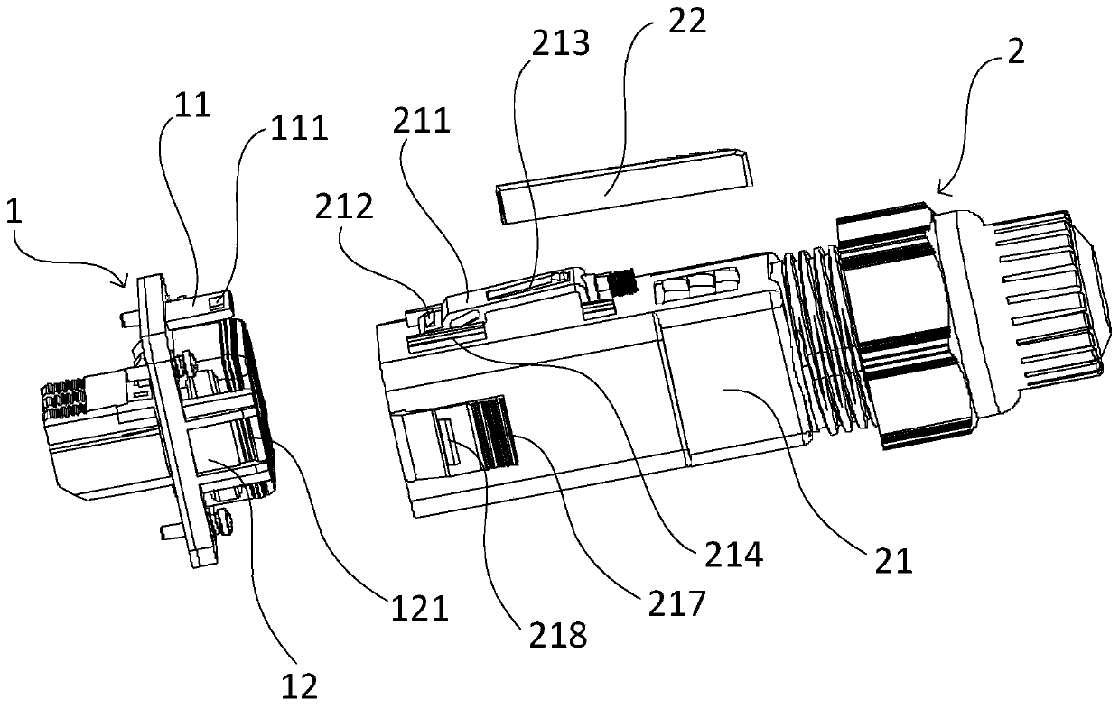
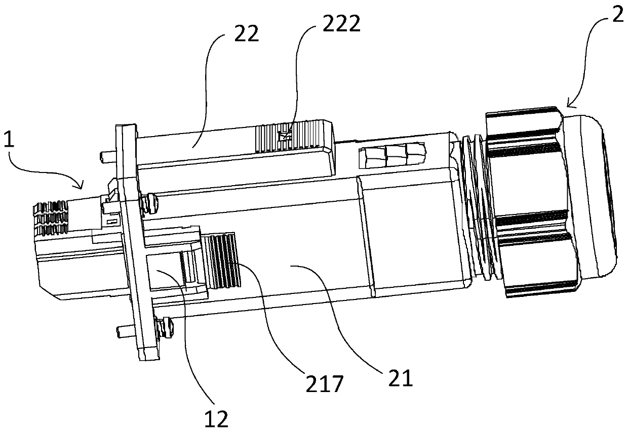
[0048] Tool unlocked connectors such as figure 1 As shown, it includes a socket 1 and a plug 2 that can be plugged and fixed with each other. The socket 1 and the plug 2 respectively have electrical connection metal parts (not shown in the figure). Socket 1 is fixed to the device housing with four screws. A socket cantilever 11 is provided on the upper side (or lower side) of the socket housing of the socket 1 near the socket, and a first card slot 111 is opened in the socket cantilever 11 .

[0049] The plug 2 includes a plug fixing housing 21 and a plug sliding housing 22 . The upper side (or lower side) corresponding to the socket cantilever 11 in the plug fixed shell 21 is provided with a plug cantilever 211, one end of the plug cantilever 211 is fixedly connected with the plug fixed shell 21, and the other end is provided with the first card slot 111. The first buckle 212 engaged with each other.

[0050] A tool unlocking structure is provided between the plug sliding...

Embodiment 2

[0073] The structure of the tool unlocking connector in embodiment 2 is basically the same as that in embodiment 1, the differences are as Figure 8 , 9 Shown:

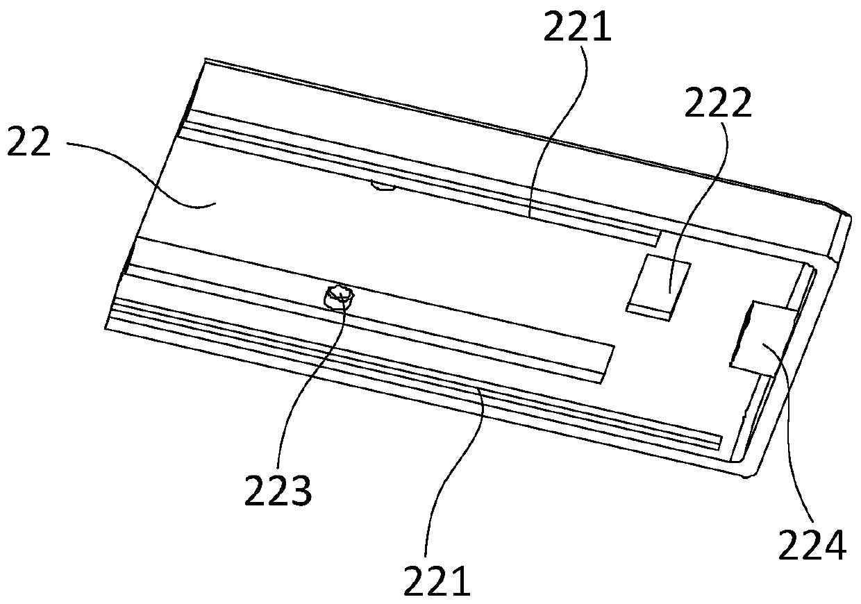
[0074] The pressing part is a driving chute 223' (abbreviated as "active chute 223'"), and the active chute 223' is respectively opened on both sides of the inside of the plug sliding housing 22, and the length of the active chute 223' is The direction is inclined downward along the plugging direction, and the inclination angle is 10°-15°. The pressed part is a driven sliding column 215' (referred to as "passive sliding column 215'"), and the passive sliding column 215' is respectively disposed on two sides of the plug cantilever 211 close to the first buckle 212. The passive sliding column 215' is located in the active chute 223' and the two can slide relative to each other.

[0075] Its working principle is: when the active chute 223' is accompanied by the plug sliding shell 22 relative to the plug fixed shell 21...


PUM

PropertyMeasurementUnit
Lengthaaaaaaaaaa
Widthaaaaaaaaaa

Abstract

The invention discloses a tool unlocking type connector. The tool unlocking type connector comprises a socket and a plug, wherein the socket and the plug are mutually inserted and fixed; a socket cantilever is arranged on the upper side or the lower side of a socket shell, close to a plug-in interface, of the socket; a first clamping groove is formed in the socket cantilever; a first clamping buckle clamped with the first clamping groove is arranged at one end of the plug cantilever; a tool unlocking structure is arranged between a sliding plug shell and a fixed plug shell; a pressing piece capable of pressing the plug cantilever is arranged on the inner side of the sliding plug shell; and a pressed piece matched with the pressing piece is arranged on the plug cantilever. The tool unlocking type connector overcomes the related defects that in the prior art, a special unlocking tool needs to be specially configured, or an independent movable accessory is easy to lose, the use is troublesome and the like.

Description

technical field [0001] The invention relates to the field of photovoltaic connectors, in particular to a tool-unlockable connector. Background technique [0002] In the existing field of photovoltaic connectors, it is stipulated that the connection structure of "tool unlocking" must be adopted between the plug and the socket. After the plug and the socket are mated, they cannot be opened by hand without the use of tools to avoid the risk of misoperation. There are usually two ways to implement the tool unlocking function. One is to use a specially designed buckle and unlocking pliers, which is mainly for small-sized connectors and requires a special unlocking tool; the other is to use the unlocking handle on the plug Insert the movable slider at the bottom. The movable slider is an accessory independent of the plug. This method is troublesome to use, and the independent accessory is easy to lose. Contents of the invention [0003] The purpose of the present invention is t...

Claims


Application Information

Patent Timeline
IPC IPC(8): H01R43/26
CPCH01R43/26
Inventor 马军亮徐玲
Owner WEIDMULLER INTERFACE SHANGHAI
Why Eureka
Try Eureka