A chain link connection structure and wearable device

A connection structure and wearable device technology, applied in bracelets, watch straps, clothing, etc., can solve problems such as high production costs, stress concentration, and complex manufacturing processes

Active Publication Date: 2021-04-02
NUBIA TECHNOLOGY CO LTD
View PDF6 Cites 0 Cited by
  • Summary
  • Abstract
  • Description
  • Claims
  • Application Information

AI Technical Summary

Problems solved by technology

[0002] At present, with the development of smart wearable devices, especially under the trend of continuous development and breakthrough of flexible screen technology, people are also constantly pursuing the wearing connection of smart watches and smart bracelets; and in the existing technology, smart wearable devices The display area is distributed on the casing, and LCD screens are used. For large-area OLED flexible screens, it is not enough to just place them on the casing, and it needs to be extended to the strap; for most smart wearable devices, the straps are mostly made It is usually processed by powder metallurgy or computer digital control precision machining CNC. There is a problem of stress concentration in the process

Method used


Image

  • A chain link connection structure and wearable device
  • A chain link connection structure and wearable device
  • A chain link connection structure and wearable device

Examples


no. 1 example

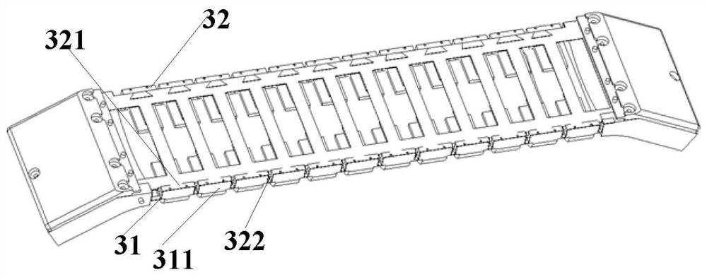
[0062] This embodiment provides a chain link connection structure, which is used for wearing links of wearable devices, such as Figure 3-1 , Figure 3-2 As shown, the chain link connection structure 30 includes at least two chain links 31, and a T-shaped steel sheet 32 ​​arranged between two adjacent chain links 31, that is, the steel sheet is "T" shaped, wherein the T-shaped steel sheet 32 includes at least two flat surfaces 321 fitted to the upper end 311 of the chain link 31, and a hollow vertical piece 322 extending along the flat surface 321 to the height direction; at least two flat surfaces 321 are connected by a vertical piece 322, and the vertical piece 322 is matched with the gap between two adjacent chain links 31; that is, the T-shaped steel sheet 32 ​​can be inserted between the gaps of two adjacent chain links 31, and the straight surface 321 and the upper end 311 of the chain link 31 face and then connect the two chain links 31.

[0063] In this embodiment, t...

no. 2 example

[0071] This embodiment provides a wearable device, such as Figure 11 As shown, it includes at least a display screen 1101, and a chain link connection structure 30 located under the display screen 1101 as in the above-mentioned embodiments. The display screen 1101 is fixedly connected to the chain link connection structure 30, through which the chain link connection structure 30 can realize wearable Wearing of the device; the display screen 1101 may include a flexible screen, and the flexible screen is set in such a way that the flexible screen is also bent correspondingly when the device is worn.

[0072] The chain link connection structure 30 includes at least two chain links 31, and a T-shaped steel sheet 32 ​​arranged between two adjacent chain links 31;

[0073] The T-shaped steel sheet 32 ​​includes at least two flat surfaces 321 that are attached to the end faces of the chain links 31, and a hollow vertical piece 322 that extends along the flat surface 321 to the heigh...


PUM


Abstract

The invention discloses a chain link connecting structure and wearable equipment. The chain link connecting structure comprises at least two chain links, and T-shaped steel sheets arranged between thetwo adjacent chain links, wherein each T-shaped steel sheet comprises at least two flat straight surfaces which are attached to the upper end of the chain link, and a hollow vertical part which extends in the height direction along the flat straight surface; the at least two flat straight surfaces are connected through the vertical part; and the vertical part is matched with the gap between the two adjacent chain links. The problem that each joint of a watchband of the existing terminal is connected through a pin shaft is solved, and when the watchband is worn, the problem of concentrated stress in the bending process is solved; and the invention further discloses the wearable equipment, so that the problem of stress concentration in the bending process is avoided.

Description

technical field [0001] The present invention relates to the technical field of terminals, and more specifically, to a link connection structure and a wearable device. Background technique [0002] At present, with the development of smart wearable devices, especially under the trend of continuous development and breakthrough of flexible screen technology, people are also constantly pursuing the wearing connection of smart watches and smart bracelets; and in the existing technology, smart wearable devices The display area is distributed on the casing, and LCD screens are used. For large-area OLED flexible screens, it is not enough to just place them on the casing, and it needs to be extended to the strap; for most smart wearable devices, the straps are mostly made It is usually processed by powder metallurgy or computer digital control precision machining CNC. There is a problem of stress concentration in the process. Contents of the invention [0003] The technical probl...

Claims


Application Information

Patent Timeline
Patent Type & Authority Patents(China)
IPC IPC(8): A44C5/10A44C5/00
CPCA44C5/0007A44C5/0084A44C5/107
Inventor 里强王德全
Owner NUBIA TECHNOLOGY CO LTD
Why Eureka
Try Eureka