Ray splitting method, laser-based cutting method, device and system

A light, polarized light technology, applied in laser welding equipment, welding equipment, metal processing equipment, etc., can solve the problems of difficult film layers of beam splitters, inconsistent output light energy of optical paths, etc.

Active Publication Date: 2021-06-25
SHANGHAI PRECISION MEASUREMENT SEMICON TECH INC
View PDF0 Cites 0 Cited by
  • Summary
  • Abstract
  • Description
  • Claims
  • Application Information

AI Technical Summary

Problems solved by technology

[0004] The purpose of the present invention is to provide a light splitting method, a laser-based cutting method, equipment and system to solve the problem in the prior art that the output light energy of the optical path is inconsistent due to the difficulty of standard ratio splitting by the film layer of the beam splitter

Method used


Image

  • Ray splitting method, laser-based cutting method, device and system
  • Ray splitting method, laser-based cutting method, device and system
  • Ray splitting method, laser-based cutting method, device and system

Examples


Embodiment Construction

[0038] The present invention will be described in detail below in conjunction with the implementations shown in the drawings, but it should be noted that these implementations are not limitations of the present invention, and those of ordinary skill in the art based on the functions, methods, or structural changes made by these implementations Equivalent transformations or substitutions all fall within the protection scope of the present invention.

[0039] The technical solutions provided by various embodiments of the present invention will be described in detail below in conjunction with the accompanying drawings.

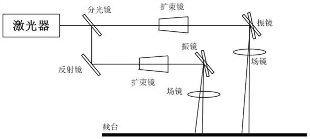
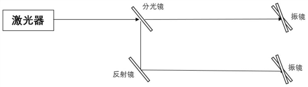
[0040] For the beam splitter (Beam Splitter), it splits the light through the surface coating. However, on the one hand, it is difficult for the film layer to achieve the standard 50:50 ratio of light splitting. Therefore, the output light energy of the two optical paths is inconsistent and the ratio is different. Larger, when laser cutting, the cutting effect is...


PUM

PropertyMeasurementUnit
angle of incidenceaaaaaaaaaa

Abstract

The invention provides a light splitting method, laser-based cutting method, equipment and system. The method includes acquiring the incident ray polarized light; controlling the incident ray polarized light to enter the first wave plate to obtain the outgoing ray polarized light; controlling the outgoing ray polarized light The light is incident on the first polarization beam splitter, and the first target light and the second target light are obtained by decomposing the polarization light of the outgoing line based on the first polarization beam splitter. The amplitude of the first target light is the cosine value of the angle between the amplitude of the polarization light of the outgoing line and the third angle The amplitude of the second target ray is the product of the amplitude of the outgoing ray polarized light and the sine of the third included angle, and the third included angle is the included angle between the outgoing ray polarized light vector and the first target ray. The present invention solves the problem of inconsistency in the output light energy of the optical path and the inability to flexibly control the independent switches of multiple optical paths because the film layer of the beam splitter is difficult to achieve standard ratio light splitting in the prior art. .

Description

technical field [0001] The invention relates to the field of light cutting, in particular to a light cutting method, a laser-based cutting method, equipment and a system. Background technique [0002] Laser cutting is generally widely used in the panel cutting industry. Due to the low power required for process processing and the high price of lasers, the laser is divided by the principle of light splitting to cut the panel according to the divided light. Generally, the schematic diagram of the equipment for cutting by laser is as follows: figure 1 As shown, it may include a laser, a beam splitter, a beam expander, a galvanometer, a field lens, and a stage. And this equipment usually utilizes a half-transparent mirror (that is, a beam splitter) to split the laser light, such as figure 2 As shown, the surface of fused silica is coated with a semi-transparent and semi-reflective film layer, which splits light through the surface coating, the incident angle is 45 degrees, an...

Claims


Application Information

Patent Timeline
Patent Type & Authority Patents(China)
IPC IPC(8): G02B27/28
CPCB23K26/067B23K26/38G02B27/283G02B27/286
Inventor 林圆圆李生强
Owner SHANGHAI PRECISION MEASUREMENT SEMICON TECH INC
Why Eureka
Try Eureka