Supercharge Your Innovation With Domain-Expert AI Agents!

Multifunctional comb

A multi-functional, comb technology, used in hair combs, clothing, hairdressing equipment, etc.

Pending Publication Date: 2019-11-01
ZHEJIANG MEISEN ELECTRICAL APPLIANCE
View PDF0 Cites 0 Cited by
  • Summary
  • Abstract
  • Description
  • Claims
  • Application Information

AI Technical Summary

Problems solved by technology

[0003] Most of the comb teeth on the market today are fixed, and they simply play the role of combing hair

Method used


Image

  • Multifunctional comb
  • Multifunctional comb
  • Multifunctional comb

Examples


Embodiment Construction

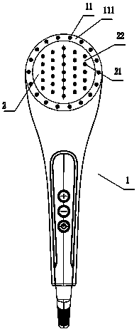
[0022] The present invention will be further described below in conjunction with the accompanying drawings: as shown in the figure, a multifunctional comb includes a housing 1, the housing is provided with a rotating plate 2 that can rotate along its own axis, and the rotating plate is provided with There are at least two comb teeth 21, and a clamping groove 22 for passing a curly hair is formed between two adjacent comb teeth.

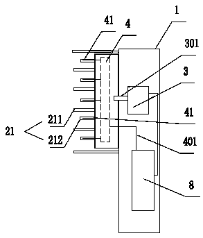
[0023] As one of the options, the rotating plate can be driven by a power source, such as figure 2 As shown, the transmission shaft 301 of the motor is connected to the pin shaft 201 on the back of the rotating plate, which can be connected through a coupling.

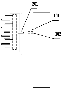
[0024] It can also be directly hinged on the shell, such as image 3 As shown, a hinged seat 101 is provided on the housing, and a hinged hole is provided on the hinged seat, and then the pin shaft 201 on the back of the rotating plate can be inserted, and the axial limit can be realized by ...


PUM


Abstract

The invention relates to a multifunctional comb which mainly solves the problem that the existing comb on the market only has a simple hair combing effect. The multifunctional comb is characterized inthat a rotating plate (2) capable of rotating around the self axis is arranged on a casing; at least two comb teeth (21) are arranged on the rotating plate; and a clamping groove (22) for a lock of hair to pass through is formed between the two adjacent comb teeth. The multifunctional comb provided by the invention is provided with the rotatable rotating plate; and the comb teeth are arranged onthe rotating plate, so that the hair curling and hair combining effects can be achieved.

Description

technical field [0001] The invention belongs to the field of daily necessities, in particular to a multifunctional comb. Background technique [0002] Hair combing is an integral part of grooming, and correct hair combing can beautify the appearance, protect the hair, and protect the brain. [0003] The comb teeth of the combs on the market are mostly fixed, and they simply play the role of combing hair. Contents of the invention [0004] In order to overcome the disadvantages of the background technology, the present invention provides a multifunctional comb, which mainly solves the problem that most of the comb teeth on the market are fixed, and they simply play the role of combing hair. [0005] The technical scheme adopted in the present invention is: [0006] A multi-functional comb, comprising a housing, the housing is provided with a rotating plate that can rotate along its own axis, the rotating plate is provided with at least two comb teeth, and a comb is formed...

Claims


Application Information

Patent Timeline
Patent Type & Authority Applications(China)
IPC IPC(8): A45D20/48A45D24/10A45D2/36
CPCA45D20/48A45D2/36A45D24/10
Inventor 虞智武
Owner ZHEJIANG MEISEN ELECTRICAL APPLIANCE
Features
  • R&D
  • Intellectual Property
  • Life Sciences
  • Materials
  • Tech Scout
  • Unparalleled Data Quality
  • Higher Quality Content
  • 60% Fewer Hallucinations
Learn More