
Tool adapter for a rotary tool

A technology of adapters and tools, applied in the direction of manufacturing tools, stone processing tools, stone processing equipment, etc., can solve problems such as loosening, removing cutting heads, and harmful efficiency

Active Publication Date: 2019-12-03
CATERPILLAR PAVING PROD INC
View PDF7 Cites 0 Cited by
  • Summary
  • Abstract
  • Description
  • Claims
  • Application Information

AI Technical Summary

Problems solved by technology

[0004] It has been observed that it is sometimes difficult to remove cutting bits from tool adapters known in the art
It has also been observed that wear, especially uneven wear is sometimes detrimental to the efficiency of machines using rotary tools
Additionally, it has been determined that some tool adapters do not have the required reliability as their connection to the rotating cutting tool may loosen over time due to vibration

Method used


Image

  • Tool adapter for a rotary tool
  • Tool adapter for a rotary tool
  • Tool adapter for a rotary tool

Examples


Embodiment Construction

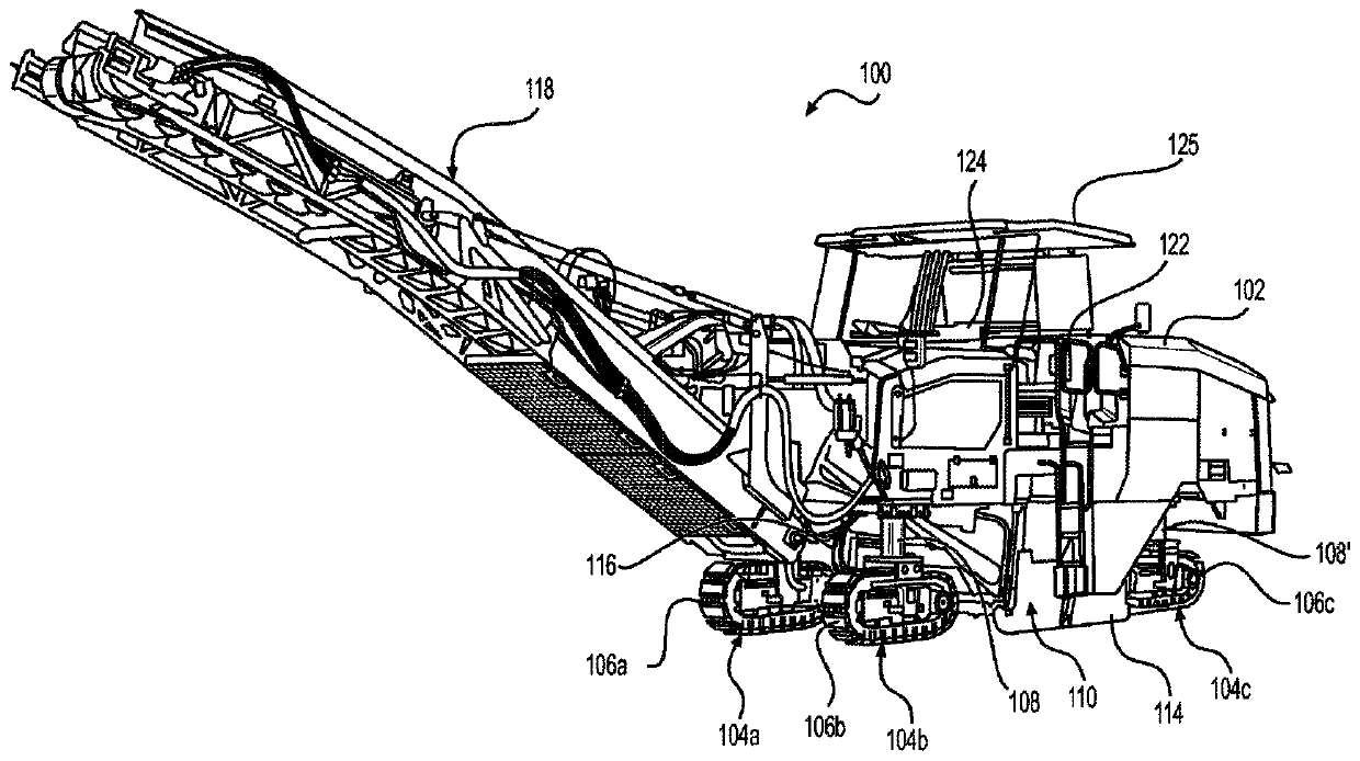
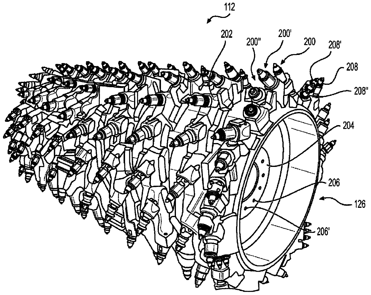
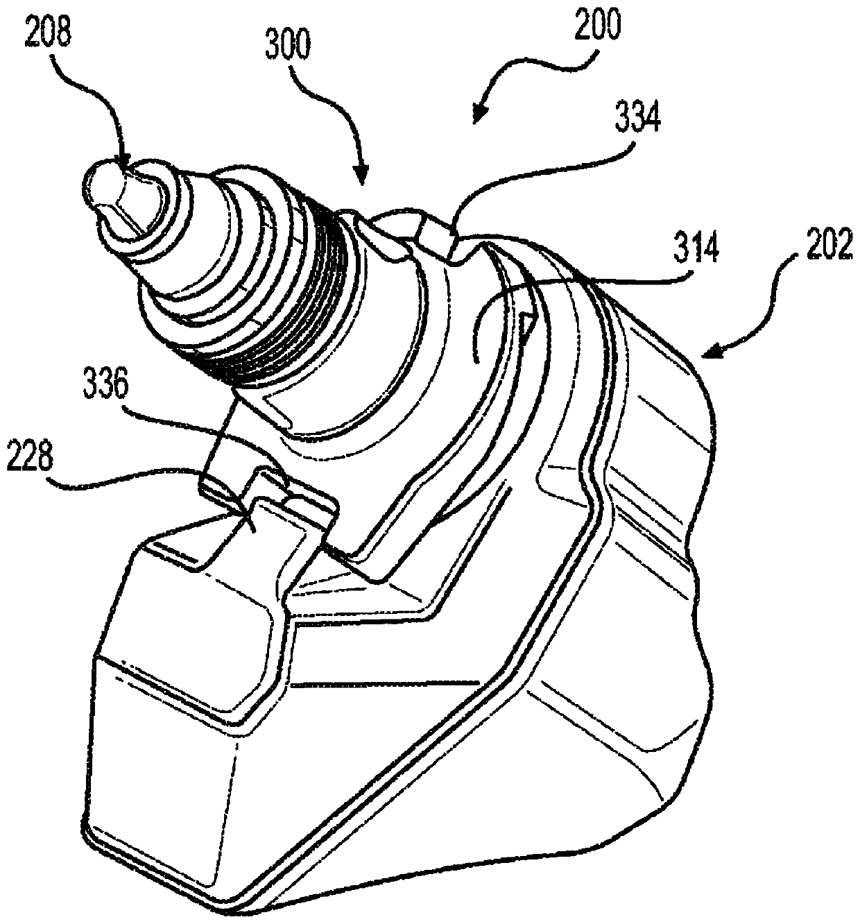
[0020] Reference will now be made in detail to embodiments of the present disclosure, examples of which are illustrated in the accompanying drawings. Wherever possible, the same reference numbers will be used throughout the drawings to refer to the same or like parts. In some instances, reference numerals will be indicated throughout this specification and drawings will show reference numerals followed by letters (eg, 100a, 100b) or primes (eg, 100', 100", etc.). The use of a letter or apostrophe following a reference number indicates that these features are of similar shape and have a similar function, which is usually the case when geometric shapes are mirrored about a plane of symmetry. For ease of explanation in this specification, letters and apostrophes are usually Not included herein, but may be shown in the drawings to indicate repetition of features discussed in this written description having similar or identical function or geometry.

[0021] Various embodiments of...


PUM


Abstract

A tool adapter (300) comprises a body (306) including at least one elongated portion (308) defining a longitudinal axis (L), a first end (310) and a second end (312) disposed along the longitudinal axis (L), a flange (314) disposed between the first and second ends (310, 312) along the longitudinal axis (L), and an exterior surface (316) extending along the longitudinal axis (L), and a collar portion (318) defining an outer collar surface (326) and the body (306) defines a first groove (328) disposed adjacent the first end (310) extending along the longitudinal axis (L) on the outer collar surface (326) along the majority of the longitudinal length of the collar portion (318).

Description

technical field [0001] The present invention relates to a tool adapter for attaching a tool such as a cutting bit to a rotating tool such as a cutting drum used in milling machines, cold planers or the like. In particular, the present invention relates to a tool adapter having features that indicate or prevent wear, facilitate removal of a cutting bit from the tool adapter, or enhance rotation of the cutting bit. Background technique [0002] Rotary tools such as cutting drums are commonly used by milling machines such as cold planers to tear away work surfaces such as soil, loose rock, asphalt, pavement, concrete. It is conceivable that these rotary tools could use cutting bits adapted to perform the necessary work. These cutting bits are prone to wear. Therefore, once worn, these cutting bits usually need to be replaced. Alternatively, it may be desirable to exchange one type of cutting bit for another, depending on the work material. For example, one cutting bit may w...

Claims


Application Information

Patent Timeline
Patent Type & Authority Applications(China)
IPC IPC(8): E21C35/197E21C35/18
CPCE21C35/197E21C35/18B28D1/186E01C23/127E01C23/088
Inventor K·J·马吉M·佩尔萨诺D·桑索内
Owner CATERPILLAR PAVING PROD INC
Learn More