An animal rear leg position control device, a milking stable provided therewith, and a rotary parlour

A control device, animal technique, applied in the first transition zone in which the first lateral side turns into the rear side defines the field

Active Publication Date: 2019-12-20
DELAVAL HLDG AB
View PDF6 Cites 2 Cited by
  • Summary
  • Abstract
  • Description
  • Claims
  • Application Information

AI Technical Summary

Problems solved by technology

As a result, the distance between the cow's hind legs is too short for a good and precise attachment of the milking unit to the cow's udder

Method used


Image

  • An animal rear leg position control device, a milking stable provided therewith, and a rotary parlour
  • An animal rear leg position control device, a milking stable provided therewith, and a rotary parlour
  • An animal rear leg position control device, a milking stable provided therewith, and a rotary parlour

Examples


Embodiment Construction

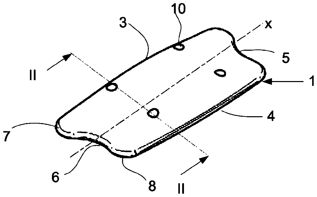
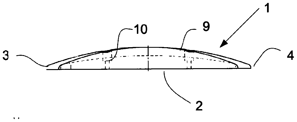
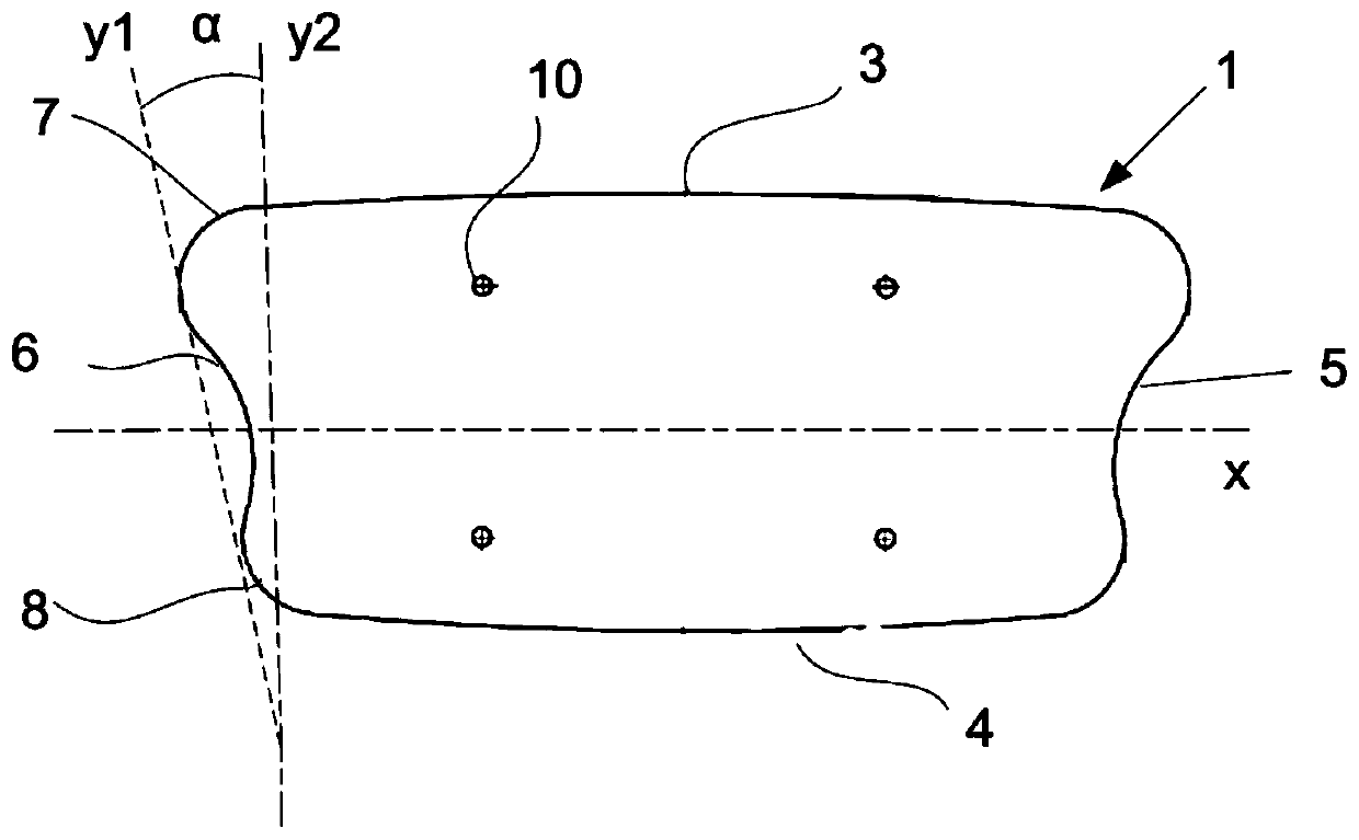
[0036] Figure 1-3 A first embodiment of an animal hind leg position control device according to the present invention is shown. The animal hind leg position control device comprises a body 1 having an underside 2 configured for an operative position resting on the floor of a milking stall. Further, the body 1 provides a first lateral side 3 and a second lateral side 4 opposite to the first lateral side 3 . Said body 1 also presents a front end 5 and a rear side 6 opposite the front end 5 , wherein the longitudinal direction of the body is defined by a line x extending from the front end 5 to the rear side 6 . The body 1 also provides a first transition area where the first lateral side 3 transitions to the rear side 6 and defines a first rear corner 7 of said body, and a second transition area where the second transition area The two lateral sides 4 transition into the rear side 6 and define a second rear corner 8 of said body 1 .

[0037] Specific as image 3 It can be s...


PUM


Abstract

An animal rear leg position control device, comprising a body (1) having a lower side (2) that is configured to rest in an operative position on a floor (14) of a milking stable, a first lateral side(3) and a second lateral side (4) that is opposite to the first lateral side (3), and a front end (5) and a rear side (6) that is opposite to the front end (5), wherein a longitudinal direction of thebody (1) is defined by a line (x) extending from the front end (5) to the rear side (6), wherein a first transition area where the first lateral side (3) turns into the rear side (6) defines a firstrear corner (7) of said body (1), and a second transition area where the second lateral side (4) turns into the rear side (6) defines a second rear corner (8) of said body (1), wherein the front end (5) is configured to be turned towards a front part of a milking stable when said body (1,101, 201) is in an operative position in the milking stable, and the rear side (6) is configured to be turned towards a rear part of a milking stable when said body (1) is in an operative position in the milking stable. The first rear corner (7) and the second rear corner (8) are positioned at different longitudinal positions in the longitudinal direction of the body (1).

Description

technical field [0001] The present invention relates to an animal hind leg position control device comprising a body having a lower side, a first lateral side and a second lateral side, and a front end and a rear side, the lower side being configured for an operative position resting on the floor of a milking stall, the second The lateral side is opposite to the first lateral side and the rear side is opposite to the front end, wherein the longitudinal direction of the body is defined by a line extending from the front end to the rear side, wherein a first transition region of the first lateral side into the rear side defines the body's A first rear corner, and a second transition region where the second lateral side turns into the rear side defines a second rear corner of the body, wherein the front end is configured to face toward the milking stall when the body is in an operative position in a milking stall. The front part of the milking stall, and the rear side is configur...

Claims


Application Information

Patent Timeline
Patent Type & Authority Applications(China)
IPC IPC(8): A01K1/12A01K15/02
CPCA01K1/12A01K15/028A01J7/00A01K1/0613A01K1/126
Inventor M.格努特克T.扎维斯兰斯基
Owner DELAVAL HLDG AB
Why Eureka
Try Eureka