Eureka AIR delivers breakthrough ideas for toughest innovation challenges, trusted by R&D personnel around the world.

Resistance and lifting force type wind driven generator

A technology for wind turbines and support plates, which is applied to wind turbines, wind turbine combinations, wind turbines at right angles to the wind direction, etc. The effect of high utilization efficiency, increased contact area, and high utilization rate of wind energy

Inactive Publication Date: 2019-12-27
祁家琦
View PDF6 Cites 0 Cited by
  • Summary
  • Abstract
  • Description
  • Claims
  • Application Information

AI Technical Summary

Problems solved by technology

[0002] With the development of society, non-renewable fossil energy is becoming exhausted, and human beings are increasingly worried about the living environment. The use of clean and renewable energy is an inevitable choice for human society. Wind power is the earliest clean energy known to mankind. The commonly used vertical Axial wind turbines are divided into lift type and drag type. The disadvantage of lift type is that the starting rotation torque is small, and it is not easy to start. The torque is large, and the wind energy utilization efficiency curve is straight, but the efficiency is low

Method used


Image

  • Resistance and lifting force type wind driven generator
  • Resistance and lifting force type wind driven generator
  • Resistance and lifting force type wind driven generator

Examples


Embodiment Construction

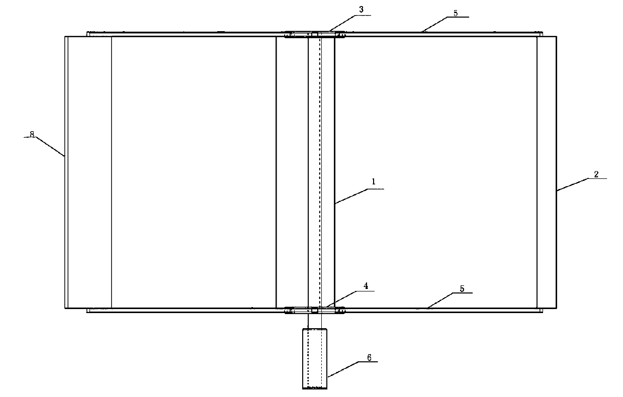
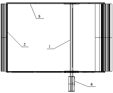
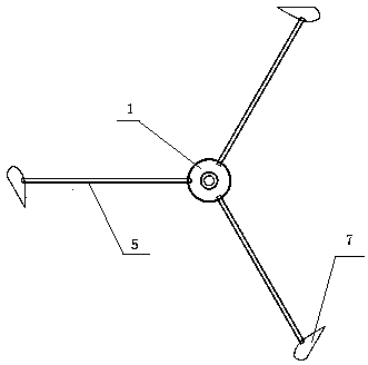
[0012] As shown in the figure, an anti-lift wind power generator includes a main shaft 1, a motor 6 is provided at the bottom of the main shaft 1, a hard connection is made between the motor 6 and the main shaft 1, an upper support plate 3 is provided at the top of the main shaft 1, and an upper support plate 3 is provided on the top of the main shaft 1. 1. There is a lower support plate 4 at the bottom. The upper and lower support plates are splined to the main shaft 1. The upper and lower support plates are ring-shaped. Support 5, three upper supports 5 are provided on the upper support plate 3, and three lower supports 5 are provided on the lower support plate 4, and the upper support and the lower support are arranged in parallel, and each upper and lower relative upper and lower supports are provided with A blade 2 in a vertical direction, the opening direction of the three blades 2 is the same, the blade 2 includes two end plates 7 arranged in parallel up and down and an ...


PUM


Abstract

The invention belongs to the technical field of wind driven generators, and particularly discloses a resistance and lifting force type wind driven generator. The resistance and lifting force type winddriven generator comprises a main shaft, wherein a motor is arranged at the bottom of the main shaft, an upper supporting disc is arranged at the top end of the main shaft, a lower supporting disc isarranged at the bottom end of the main shaft, the upper supporting disc and the lower supporting disc are connected through a spline and are ring-shaped, each supporting disc is provided with three supports along the circumference uniformly in the horizontal direction, three upper supports are arranged on the upper supporting disc, three lower supports are arranged on the lower supporting disc, the upper supports and the lower supports are parallel, a blade in the vertical direction is arranged between each upper support and the corresponding lower support which are opposite vertically, and starting directions of the three blades are the same. According to the invention, a lifting force type wind driven generator and a resistance type wind driven generator are integrated simultaneously, meanwhile, functions of both the lifting force type wind driven generator and the resistance type wind driven generator are obtained, advantages of both the lifting force type wind driven generator andthe resistance type wind driven generator are integrated, and the utilization efficiency of wind power is high.

Description

technical field [0001] The invention belongs to the technical field of wind power generators, in particular to a drag-lift wind power generator. Background technique [0002] With the development of society, non-renewable fossil energy is becoming exhausted, and human beings are increasingly worried about the living environment. The use of clean and renewable energy is an inevitable choice for human society. Wind power is the earliest clean energy known to mankind. The commonly used vertical Axial wind turbines are divided into lift type and drag type. The disadvantage of lift type is that the starting rotation torque is small, and it is not easy to start. The torque is large, and the wind energy utilization efficiency curve is straight, but the efficiency is low. Contents of the invention [0003] The object of the present invention is to provide a drag-type wind power generator, which integrates the lift-type wind power generator and the drag-type wind power generator s...

Claims


Application Information

Patent Timeline
Patent Type & Authority Applications(China)
IPC IPC(8): F03D9/25F03D3/06
CPCF03D9/25F03D3/005F03D3/062Y02E10/74
Inventor 祁家琦
Owner 祁家琦
Why Eureka
Eureka Blog
Learn More