A cross-arrangement method of gas-fired boiler flue gas latent heat recovery device

A recovery device, gas boiler technology, applied in the direction of air heaters, fluid heaters, lighting and heating equipment, etc., can solve the problem that there is no clear method for condensing boilers, the time of condensing boilers is short, and the thermal calculation method is not suitable for the design of waste heat recovery devices And other issues

Active Publication Date: 2021-04-27
CHINA SPECIAL EQUIP INSPECTION & RES INST
View PDF6 Cites 0 Cited by
  • Summary
  • Abstract
  • Description
  • Claims
  • Application Information

AI Technical Summary

Problems solved by technology

[0002] In order to recover the latent heat of vaporization in the flue gas generated by gas combustion, natural gas boilers have generally been equipped with condensers and air preheaters in recent years. However, due to the short use time of condensing boilers in my country, mature design concepts have not yet been fully formed. This is reflected in the fact that so far, there is no design method or standard for condensing boilers in my country. In particular, there is no clear method in the industry on how to arrange the heating surface at the tail of the condensing boiler. The main reason is that when the condenser and the air preheater are arranged crosswise, Due to the latent heat of vaporization released by water vapor, the water vapor turns into liquid water, so the traditional thermal calculation method is no longer suitable for the design of such waste heat recovery devices

Method used


Image

  • A cross-arrangement method of gas-fired boiler flue gas latent heat recovery device
  • A cross-arrangement method of gas-fired boiler flue gas latent heat recovery device
  • A cross-arrangement method of gas-fired boiler flue gas latent heat recovery device

Examples


Embodiment Construction

[0025] The technical solutions in the embodiments of the present invention will be clearly and completely described below in conjunction with the drawings in the embodiments of the present invention.

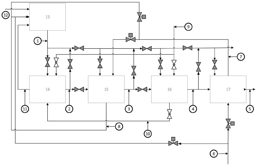
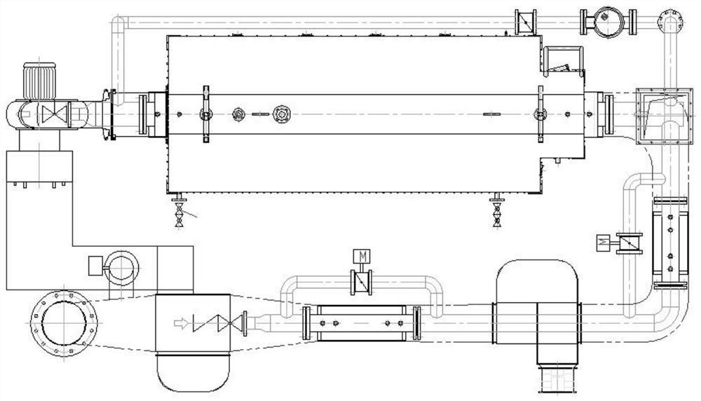
[0026] see Figure 1-2 Describe this embodiment, a gas boiler flue gas latent heat recovery device cross arrangement method, the flue gas outlet of the gas boiler 13 is connected to the latent heat recovery device, and the latent heat recovery device includes multiple condensers and multiple air preheaters , the plurality of condensers and the plurality of air preheaters are arranged crosswise in turn, the flue gas side, the air side and the working fluid side of the latent heat recovery device are measured respectively by sensors, and the plurality of condensers and multi-stages are respectively drawn according to the measurement data The performance curve of each air preheater, the area formed by the performance curves of all condensers and air preheaters is the layout area of...


PUM


Abstract

The invention provides a cross-arrangement method of gas-fired boiler flue gas latent heat recovery devices, which belongs to the technical field of design of a heating surface at the rear of a gas-fired boiler, and in particular relates to a cross-arrangement method of gas-fired boiler flue gas latent heat recovery devices. The problem that the traditional thermal calculation method is not suitable for the design of the latent heat recovery device on the heating surface of the boiler tail is solved. The latent heat recovery device described in this method includes multiple condensers and multiple air preheaters, and the flue gas side, the air side and the working medium side of the latent heat recovery device are measured, and multiple condensers and multiple The performance curve of the air preheater, the area formed by the performance curves of all condensers and air preheaters is the layout area of ​​the heating surface at the rear of the gas boiler, and the condenser and air preheater corresponding to the comprehensive performance curve with the largest comprehensive performance value are selected. The arrangement of the heaters is used as the arrangement structure of the latent heat recovery device. It is mainly used in the layout design of the heating surface at the tail of the gas boiler.

Description

technical field [0001] The invention belongs to the technical field of design of a heating surface at the rear of a gas boiler, and in particular relates to a cross arrangement method of latent heat recovery devices for flue gas of a gas boiler. Background technique [0002] In order to recover the latent heat of vaporization in the flue gas generated by gas combustion, natural gas boilers have generally been equipped with condensers and air preheaters in recent years. However, due to the short use time of condensing boilers in my country, mature design concepts have not yet been fully formed. This is reflected in the fact that so far, there is no design method or standard for condensing boilers in my country. In particular, there is no clear method in the industry on how to arrange the heating surface at the tail of the condensing boiler. The main reason is that when the condenser and the air preheater are arranged crosswise, Because the water vapor releases the latent heat o...

Claims


Application Information

Patent Timeline
Patent Type & Authority Patents(China)
IPC IPC(8): F24H8/00F24H9/00F24H9/20
CPCF24H8/00F24H9/0005F24H9/0036F24H9/2035Y02B30/00
Inventor 齐国利刘雪敏于吉明张松松
Owner CHINA SPECIAL EQUIP INSPECTION & RES INST
Why Eureka
Try Eureka