Double-drive structure of roller cam single-output shaft

A technology of roller cam and output shaft, which is applied in the direction of metal processing machinery parts, metal processing, metal processing equipment, etc. It can solve the problems of affecting the indexing precision of the rotary table, difficult space configuration, and enlarging the volume of the servo motor.

Inactive Publication Date: 2020-01-24
福建鑫鋐笙精密机械有限公司
View PDF9 Cites 0 Cited by
  • Summary
  • Abstract
  • Description
  • Claims
  • Application Information

AI Technical Summary

Problems solved by technology

[0002] With the advancement of manufacturing technology, the machinery and equipment that people use every day are becoming more and more complex, and machinery-related industries are inevitably moving towards the goal of high precision and high efficiency; among them, the development of numerical control machinery is an indispensable part. Numerical control The accuracy of the rotary table will directly affect the machining accuracy of the numerically controlled machine. The rotary table of the commonly known numerically controlled machine is driven by a servo motor. , and the deceleration mechanism will inevitably produce a backlash between the transmission meshes, thus affecting the indexing precision of the rotary table
[0003] However, in order to increase the torsion of the output shaft, the conventional driving structure usually increases the coil of the servo mo...

Method used


Image

  • Double-drive structure of roller cam single-output shaft
  • Double-drive structure of roller cam single-output shaft
  • Double-drive structure of roller cam single-output shaft

Examples


Embodiment Construction

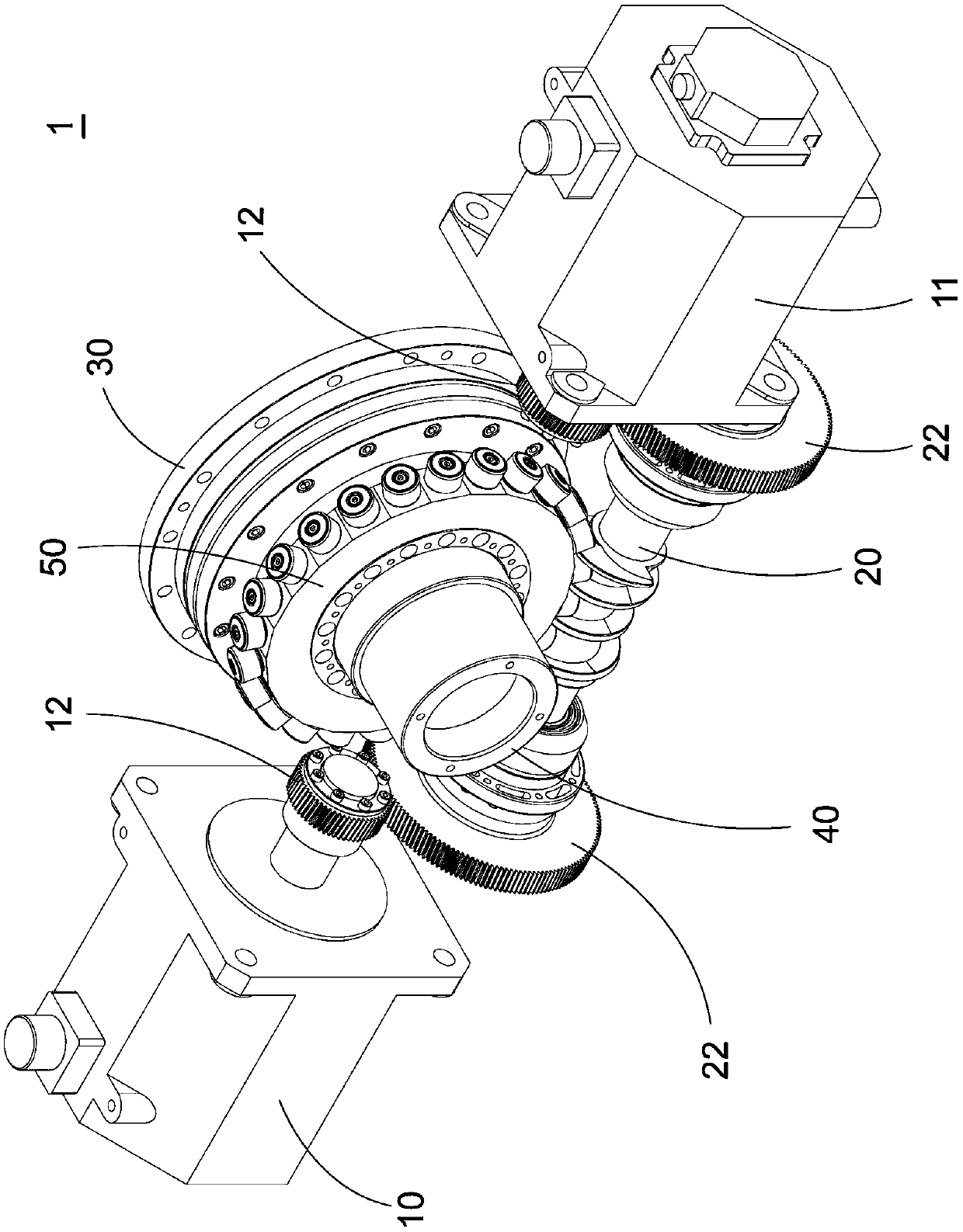
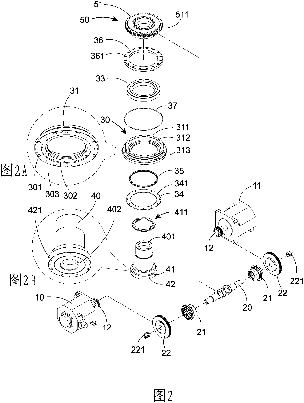
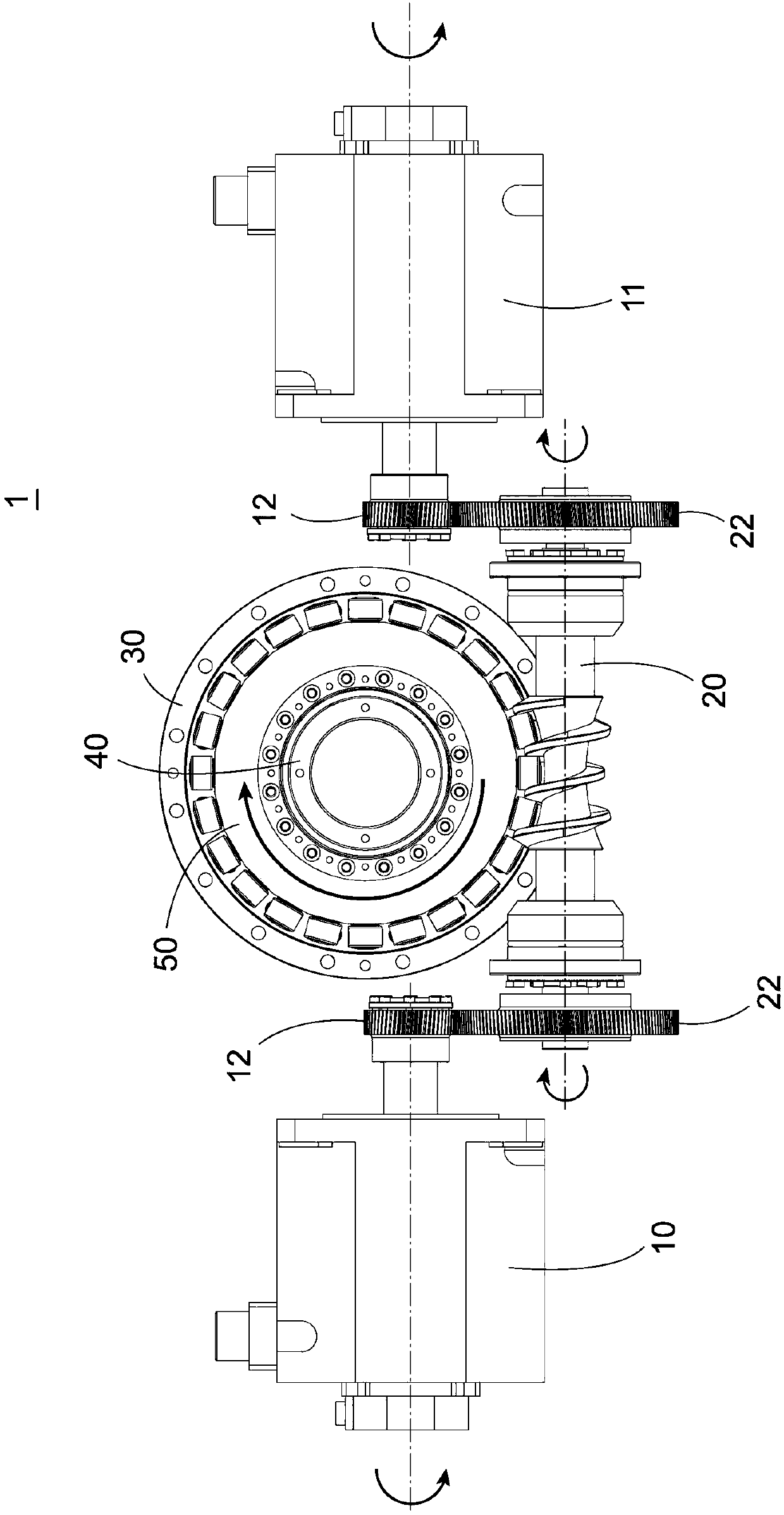
[0029] see Figure 1 to Figure 4 As shown, the preferred embodiment of the dual drive structure of the roller cam single output shaft of the present invention, but these embodiments are for illustration purposes only, and are not limited by this structure in patent applications, which include:

[0030] see Figure 1 to Figure 2 As shown, a double drive structure 1 with a roller cam and a single output shaft is used to give a driving force to a turning-milling composite swing head or a rotary table (index plate) of a horizontal processing machine, which includes A main power base 10 and at least one auxiliary power base 11, the output axis of the auxiliary power base 11 is parallel to the output axis of the main power base 10, the main power base 10 and the auxiliary power base 11 are respectively connected with a power wheel 12, The main power base 10 and the auxiliary power base 11 are driving motors, and the driving motors are controlled by a computer numerical control syst...


PUM


Abstract

The invention relates to a double-drive structure of a roller cam single-output shaft. The structure comprises a main power base, auxiliary power bases parallel to the main power base, power wheel connected with power bases, camshafts, driven wheels which are arranged on the camshafts and correspondingly meshed with the power wheels, and a main output shaft with a roller assembly, the main power base and the auxiliary power base are controlled synchronously by numerical control to simultaneously transmit equal power to the corresponding power wheels, the power wheels drive the corresponding driven wheels, and the two ends of the camshafts are driven to rotate stably, so that the camshafts act the roller assembly and is connected with the main output shaft to achieve synchronous action of main power base and auxiliary power base, and the purposes of improving the torque of the main output shaft and reducing the weight of a drive motor.

Description

technical field [0001] The present invention relates to a double-drive structure, especially a double-drive structure with a roller cam and a single output shaft. By means of a computer digital control system, a main power seat and an auxiliary power seat are synchronously actuated to simultaneously transmit equal The power is on a corresponding power wheel, and each power wheel drives a corresponding driven wheel, so that both ends of a camshaft are evenly stressed and rotate stably, so that the camshaft actuates a roller assembly and moves in unison An output main shaft is used to achieve the purpose of synchronizing the main power base and the auxiliary power base to increase the torque of the output main shaft. Background technique [0002] With the advancement of manufacturing technology, the machinery and equipment that people use every day are becoming more and more complex, and machinery-related industries are inevitably moving towards the goal of high precision and ...

Claims


Application Information

Patent Timeline
IPC IPC(8): B23Q5/00B23Q5/34
CPCB23Q5/00B23Q5/341
Inventor 张永昌
Owner 福建鑫鋐笙精密机械有限公司
Why Eureka
Try Eureka