Cooling and heat dissipation system aiming at high-temperature heat source equipment and cooling and heat dissipation method

A high-temperature heat source and cooling system technology, applied in heat exchange equipment, lighting and heating equipment, heating methods, etc., can solve problems such as the inability to meet the thermal comfort needs of workers, the inability to ensure uniform temperature field distribution, and the harsh thermal environment. Significant economic and social value, meeting thermal comfort requirements, and improving thermal environment

Pending Publication Date: 2020-02-07
NANHUA UNIV
View PDF0 Cites 1 Cited by
  • Summary
  • Abstract
  • Description
  • Claims
  • Application Information

AI Technical Summary

Problems solved by technology

[0005] The purpose of the present invention is to overcome the deficiencies of the prior art, and provide a cooling system and a cooling and cooling method for high-temperature heat source equipment, which solves the problem of the poor thermal environment of industrial plants and the use of air conditioners to cool and heat high-temperature heat source equipment. Large capacity, unable to ensure the uniform distribution of temperature field in each area of ​​the factory building and unable to meet the thermal comfort needs of workers

Method used


Image

  • Cooling and heat dissipation system aiming at high-temperature heat source equipment and cooling and heat dissipation method
  • Cooling and heat dissipation system aiming at high-temperature heat source equipment and cooling and heat dissipation method
  • Cooling and heat dissipation system aiming at high-temperature heat source equipment and cooling and heat dissipation method

Examples


Embodiment 1

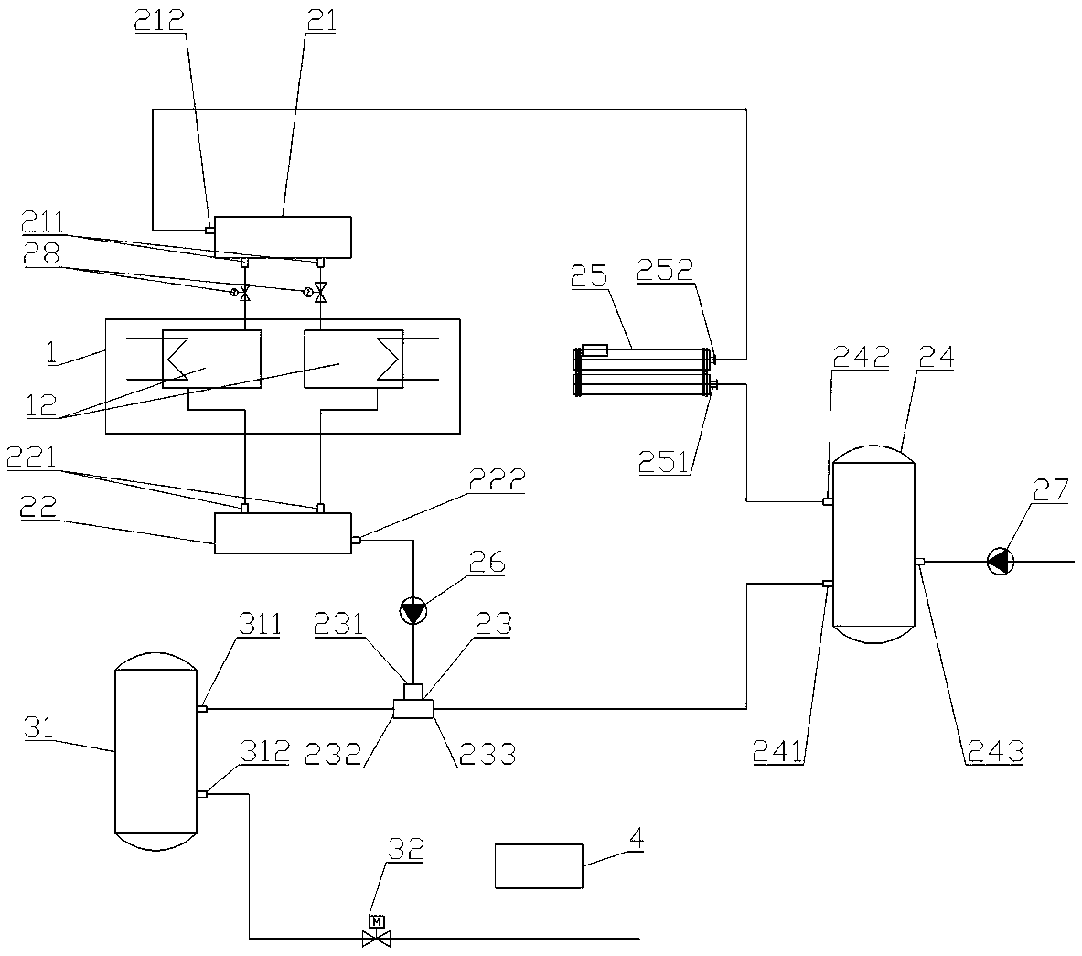
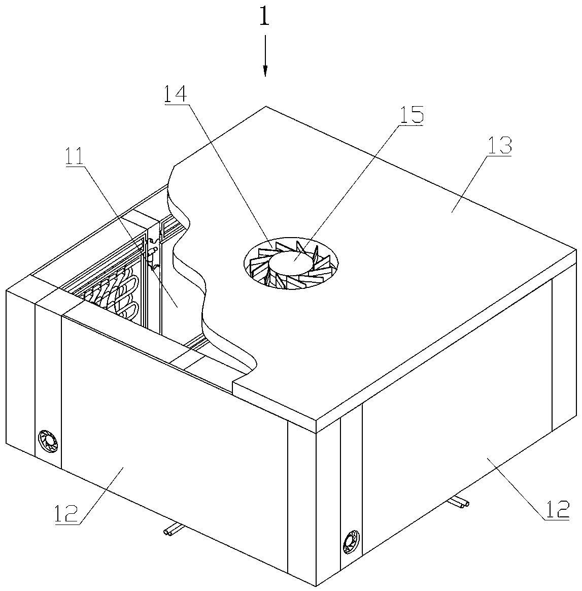
[0053] Such as Figure 1-7 As shown, the cooling and cooling system for high-temperature heat source equipment includes a thermal insulation cooling cover 1, a water cooling circulation device and a hot water distribution device.

[0054] The heat insulation and cooling cover 1 is in the shape of a hollow prism, and there is an equipment placement cavity 11 inside, which is constructed by a side wall composed of a heat insulation cooling wall 12 and a top wall composed of a heat insulation board 13 . The top wall is provided with an air outlet 14 connecting the inside and outside of the heat insulation and cooling cover 1 , and an exhaust fan 15 is installed on the air outlet 14 .

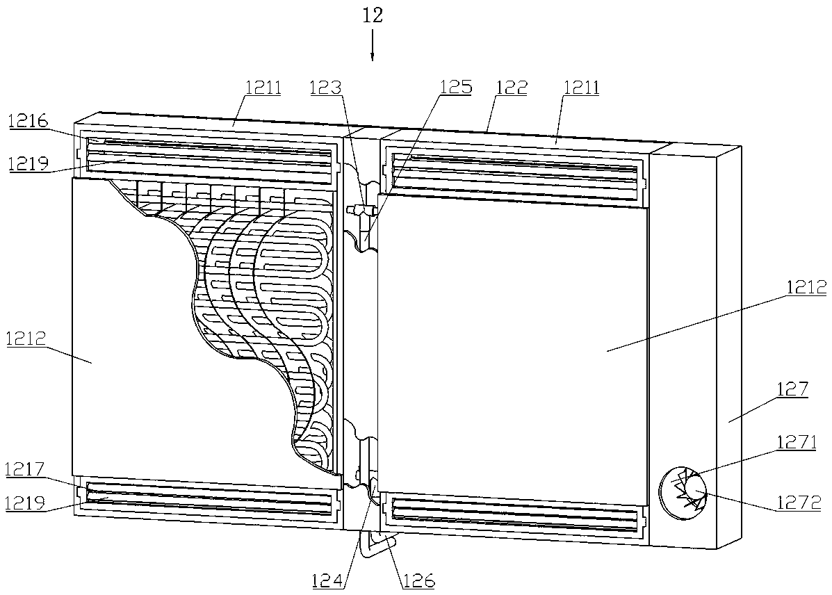
[0055] The heat insulating and cooling wall 12 includes a wall unit 121 , a backboard 122 , a tee joint A123 , a tee joint B124 , an input pipe 126 , an output pipe 125 and an air inlet chamber 127 .

[0056] The wall unit 121 includes a heat insulating shell 1211 , a radiation metal plate 1212 , ...


PUM


Abstract

The invention relates to a cooling and heat dissipation system aiming at high-temperature heat source equipment. The system comprises a heat insulation cooling cover, a water cooling circulating device and a hot water diversion device, wherein the heat insulation cooling cover is formed by building a side wall composed of a heat insulation cooling wall and a top wall composed of a heat insulationplate, and the heat insulation cooling wall comprises a wall unit. The cooling and heat dissipation method aimed at the high-temperature heat source equipment comprises the following steps that the heat insulation cooling cover is built outside the high-temperature heat source equipment; an air inlet fan and an air exhaust fan are started to continuously perform cooling and heat dissipation on thehigh-temperature heat source equipment; and circulating water is enabled to flow in a circulating mode to continuously perform cooling and heat dissipation on the high-temperature heat source equipment. According to the system, the high-temperature heat source equipment is enveloped by the heat insulation cooling cover, the high-temperature heat source equipment is continuously and efficiently cooled, the temperature of a peripheral area of the high-temperature heat source equipment is effectively reduced, heat generated by the high-temperature heat source equipment is greatly reduced to be diffused to the periphery, and the situation that a local high-temperature area is formed in a factory building is avoided, so that the thermal comfort requirement of workers is met.

Description

technical field [0001] The invention relates to the field of heat dissipation and cooling systems, in particular to a cooling and heat dissipation system and a cooling and heat dissipation method for high-temperature heat source equipment. Background technique [0002] In recent years, with the development of industrial production towards refinement, integration, and intelligence, the production lines in industrial plants have become more and more compact, and the resulting problem is that the heat production in the plant has increased significantly. At the same time, some plants have high-temperature heat source equipment that produces large amounts of heat, which brings considerable technical difficulties to the cooling and heat dissipation inside the plant. [0003] How to quickly, effectively and timely remove the heat generated by the high-temperature heat source equipment inside the factory building, ensure the uniform distribution of the temperature field in each area...

Claims


Application Information

Patent Timeline
Patent Type & Authority Applications(China)
IPC IPC(8): F28D7/08F28F27/02F28F13/18F24F5/00E04B2/00E04B1/78
CPCE04B1/78E04B2/00F24F5/0003F28D7/08F28F13/18F28F27/02Y02P80/10
Inventor 蒋新波杨历全刘泽华黄春华李鹏飞金雷
Owner NANHUA UNIV
Why Eureka
Try Eureka