
Signal triggering method and system

A signal triggering and signal technology, applied in the field of data processing, can solve the problem of no identification and triggering

Active Publication Date: 2020-02-14
RIGOL
View PDF5 Cites 0 Cited by
  • Summary
  • Abstract
  • Description
  • Claims
  • Application Information

AI Technical Summary

Problems solved by technology

In the prior art, there is no scheme for identifying and triggering based on the frequency domain characteristics of the signal

Method used


Image

  • Signal triggering method and system
  • Signal triggering method and system
  • Signal triggering method and system

Examples


Embodiment Construction

[0054] The following will clearly and completely describe the technical solutions in the embodiments of the present invention with reference to the accompanying drawings in the embodiments of the present invention. Obviously, the described embodiments are only some, not all, embodiments of the present invention. Based on the embodiments of the present invention, all other embodiments obtained by persons of ordinary skill in the art without making creative efforts belong to the protection scope of the present invention.

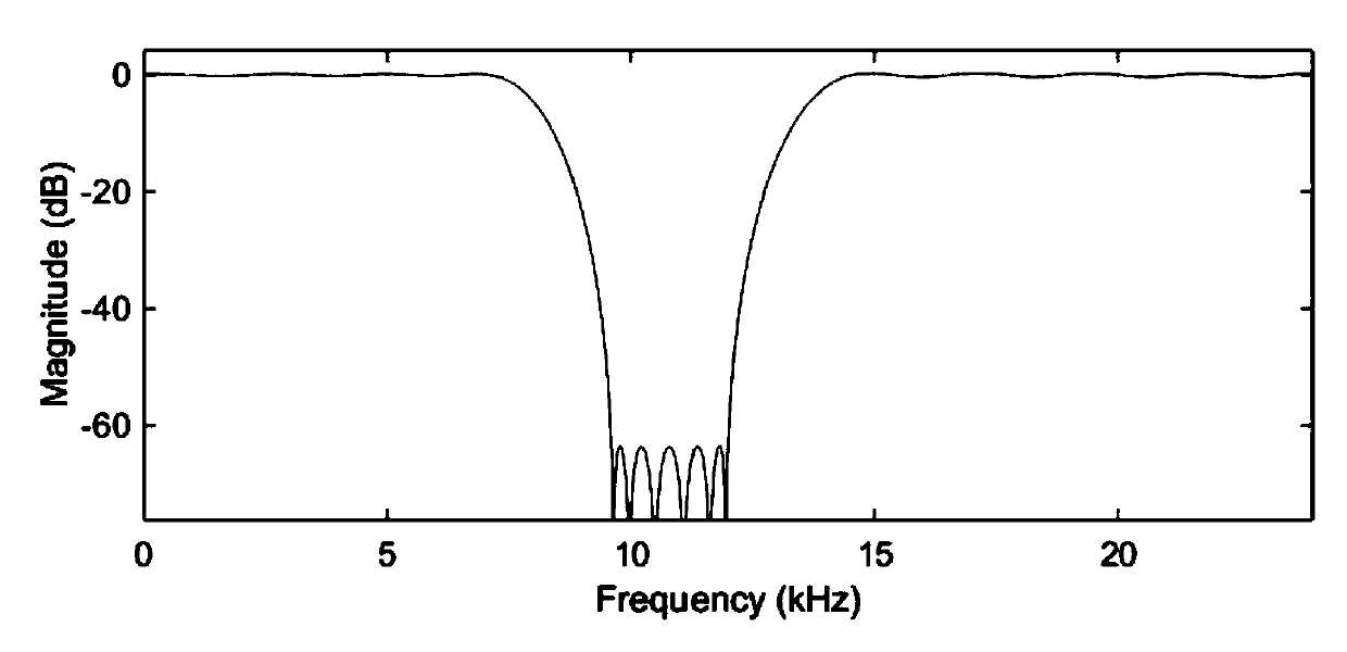
[0055] The inventors found that the amplitude attenuation of different frequency components of the signal by the filter is different, for example, the frequency response characteristics of the band-stop filter are as follows: figure 1 As shown, using the frequency response characteristics of the filter, when the user needs to trigger certain frequency components, the user can input the frequency range of the signal to be triggered and configure the correspondin...


PUM


Abstract

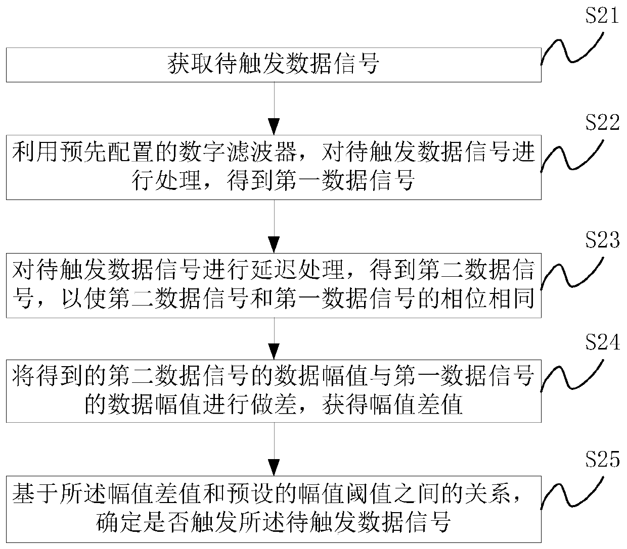
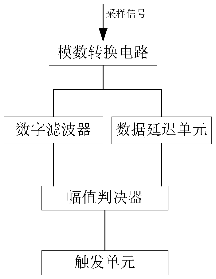
The embodiment of the invention provides a signal triggering method and system. The method comprises the following steps: 1, performing filtering processing on to-be-triggered data signal by using adigital filter, performing subtraction on data amplitude of an original to-be-triggered data signal and filtered data amplitude, and determining whether to trigger the to-be-triggered data signal by judging whether the relationship between the obtained amplitude difference and a preset amplitude threshold meets a preset condition or not. By configuring the digital filter, different types of filters can be obtained, then the to-be-triggered data signals in different frequency ranges are filtered, and the requirement of a user for triggering any specific frequency component of the signals is met.

Description

technical field [0001] The present invention relates to the technical field of data processing, and more specifically, to a signal triggering method and system. Background technique [0002] At present, identification and triggering are usually performed based on time-domain characteristics of the signal, for example, identification and triggering of rising edges or pulse widths in the signal. In the prior art, there is no solution for identifying and triggering based on the frequency domain characteristics of the signal. Contents of the invention [0003] In view of this, the present invention proposes a signal triggering method and system to achieve the purpose of identifying and triggering based on the frequency domain characteristics of the signal. [0004] In order to achieve the above purpose, the proposed scheme is as follows: [0005] In a first aspect, the present invention provides a signal trigger method, including: [0006] Obtain the data signal to be trigg...

Claims


Application Information

Patent Timeline
Patent Type & Authority Applications(China)
IPC IPC(8): H03H17/00H03H17/02
CPCH03H17/00H03H17/0009H03H17/02H03H2017/0081
Inventor 蒋文裕索世昌王悦王铁军李维森
Owner RIGOL
Learn More