Permanent magnet transmission speed change mechanism

A technology of speed change mechanism and permanent magnet transmission, applied in permanent magnet clutches/brakes, electromechanical devices, electric components, etc. The effect of long service life, volume and weight control, and high transmission efficiency

Pending Publication Date: 2020-04-24
台州市路桥鼎新阳光机电科技有限公司
View PDF3 Cites 0 Cited by
  • Summary
  • Abstract
  • Description
  • Claims
  • Application Information

AI Technical Summary

Problems solved by technology

[0002] At present, the ordinary speed change mechanism generally adopts a mechanical transmission structure, and realizes the speed change function through the gear ratio of the worm wheel, the screw, or the large and small gears. Due to the large mechanical friction of this kind of speed change mechanism, there is a large friction in the power transmission process. Problems of mechanical friction, power loss and working noise. At the same time, in order to ensure the service life of the transmission mechanism, ordinary reducers need to be filled with lubricating oil or grease for lubrication, and regular maintenance is required
Therefore, the common transmission mechanism has problems such as large power loss and short service life.

Method used


Image

  • Permanent magnet transmission speed change mechanism
  • Permanent magnet transmission speed change mechanism
  • Permanent magnet transmission speed change mechanism

Examples


Embodiment Construction

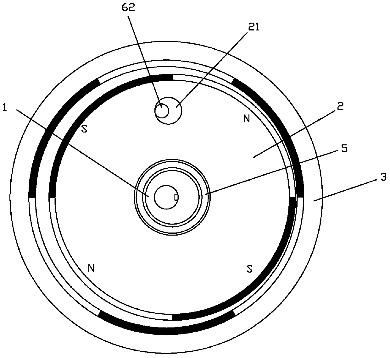
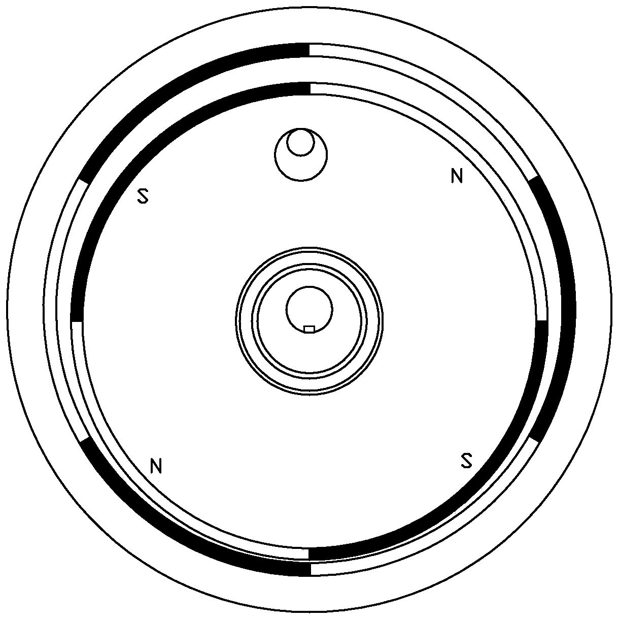
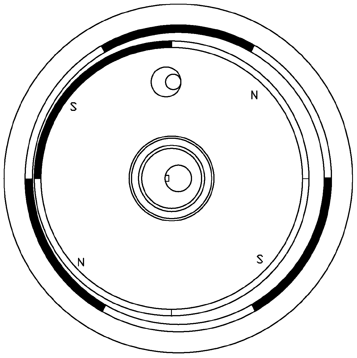
[0019] Such as Figure 1-5 As shown, a speed change mechanism of permanent magnet transmission includes an eccentric shaft 1, a swing disc 2, an outer rotor 3 and a stop mechanism, the swing disc 2 is sleeved on the outer edge of the eccentric shaft 12 through a bearing, and the outer rotor 3 Coaxially arranged on the periphery of the oscillating disk 2, an even number of permanent magnetic steel sheets are arranged on the outer peripheral surface of the oscillating disk 2 and the inner peripheral surface of the outer rotor 3, and the permanent magnetic steel sheets on the outer peripheral surface The magnetic poles of the adjacent permanent magnetic steel sheets in the inner edge surface are opposite to each other, and the magnetic poles of the adjacent permanent magnetic steel sheets in the inner edge surface of the permanent magnetic steel sheets are also opposite to each other, and the outer edge surface of the swing disk 2 and the outer rotor The number of permanent magne...


PUM


Abstract

The invention relates to a permanent magnet transmission speed change mechanism. A swing disc arranged on an eccentric shaft is matched with an outer rotor, and the number of permanent magnet steel sheets of the swing disc and the number of permanent magnet steel sheets of the outer rotor are different. When the swing disc swings in an annular shape, the rotor is made to rotate through the actingforce of opposite attraction of the permanent magnet steel sheets. The gear ratio of the speed change mechanism is determined by the difference value of the number of the permanent magnet steel sheetsarranged on the rotor and the number of the permanent magnet steel sheets arranged on the swing disc, and a large gear ratio can be easily achieved. The speed change mechanism has the advantages of quite high power transmission efficiency, large-range gear ratio, almost no mechanical friction and transmission loss during power transmission besides weak loss of the bearing, simple structure, smallvolume, low weight, no need of lubricating oil, no need of periodic maintenance, long service life and the like.

Description

technical field [0001] The invention relates to a speed change mechanism technology, in particular to a speed change mechanism for permanent magnet transmission. Background technique [0002] At present, the ordinary speed change mechanism generally adopts a mechanical transmission structure, and realizes the speed change function through the gear ratio of the worm wheel, the screw, or the large and small gears. Due to the large mechanical friction of this kind of speed change mechanism, there is a large friction in the power transmission process. Problems of mechanical friction, power loss and working noise. At the same time, in order to ensure the service life of the transmission mechanism, ordinary reducers need to be filled with lubricating oil or grease for lubrication, and regular maintenance is required. Therefore, the common transmission mechanism has problems such as large power loss and short service life. Contents of the invention [0003] The purpose of the ...

Claims


Application Information

Patent Timeline
Patent Type & Authority Applications(China)
IPC IPC(8): H02K49/10H02K7/075
CPCH02K49/102H02K7/075
Inventor 章昭晖
Owner 台州市路桥鼎新阳光机电科技有限公司
Why Eureka
Try Eureka