Cotton suction driving device for spinning frame

A driving device and spinning frame technology, applied in textile and paper making, etc., can solve the problems of unstable adsorption effect, increase equipment purchase cost, energy loss and other problems, achieve simple and easy daily maintenance, save energy costs, and reduce labor costs Effect

Inactive Publication Date: 2011-07-06
NANTONG DOUBLE GREAT TEXTILE
View PDF4 Cites 0 Cited by
  • Summary
  • Abstract
  • Description
  • Claims
  • Application Information

AI Technical Summary

Problems solved by technology

[0002] At present, all types of spinning frames in all textile mills use separate motors to directly drive the cotton suction fan through the flute tube to continuously absorb cotton yarn breakage, flying flowers, and dust. The rated power of the spinning frame suction fan is 2.2KW, 1.5KW and 1.1KW. A separate motor increases the purchase cost of the equipment, and the motor and mechanical parts also need to be maintained by electricians and security workers on a daily basis, which will increase the cost of labor. Although this driving method can have a better adsorption effect, it will cause motor Load operation produces energy loss, which increases the cost of spinning
Even though many textile mills or textile machinery factories in China have carried out energy-saving transformation of fans and used low-energy fans, the adsorption effect is unstable, and it may even cause the overload of the fans to damage the motor, which will cause unnecessary economic losses.
The rated power of the main motor of the spinning frame is 17KW, and the rated power is more than 6.5KW higher than the actual power. Once the spinning frame is in a stable running state after starting, the excess power will inevitably cause waste

Method used


Image

  • Cotton suction driving device for spinning frame
  • Cotton suction driving device for spinning frame

Examples


Embodiment Construction

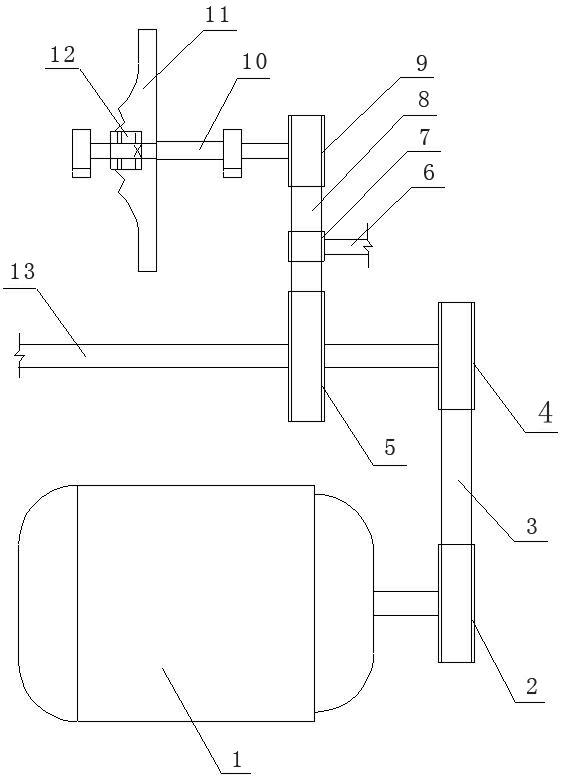
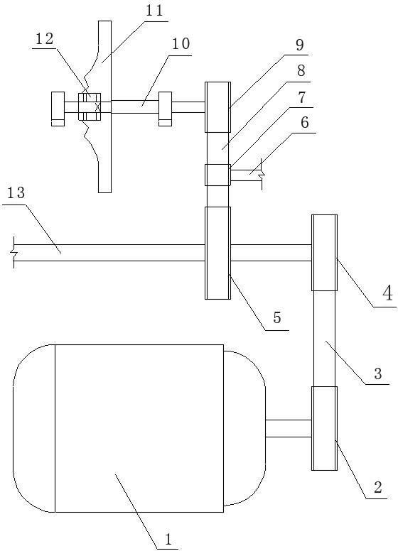
[0012] like figure 1 As shown, it is the cotton suction driving device of the spinning frame, which includes the main motor 1 of the spinning frame. The output shaft is arranged in parallel, the first driven wheel 4 and the second driving wheel 5 are connected on the main shaft 13, and the first driven wheel 4 is connected with the first driving wheel 2 through the first transmission belt 3. The upper side of the main shaft 13 is provided with an impeller shaft 10 in parallel. The second driven wheel 9 and the fan blade 11 are connected to the impeller shaft 10. The second driven wheel 9 is connected to the second driving wheel 5 through the second transmission belt 8. The fan blade 11 passes through the backstop. The device 12 is connected to the impeller shaft 10. Between the main shaft 13 and the impeller shaft 10, a rotating shaft 6 is arranged in parallel, and the rotating shaft 6 is connected with a tension pulley 7, and the tension pulley 7 is arranged on the side of t...


PUM


Abstract

The invention provides a cotton suction driving device for a spinning frame, and relates to the technical field of textile machinery, in particular to the structure of the cotton suction driving device installed on the spinning frame. The cotton suction driving device for the spinning frame comprises a main motor; a first driving wheel is connected on an output shaft of the main motor; a main shaft is arranged at the upper side of the main motor and is in parallel with the output shaft of the main motor; a first driven wheel and a second driving wheel are connected on the main shaft, and the first driven wheel is in transmission connection with the first driving wheel through a first transmission belt; an impeller shaft is arranged in parallel at the upper side of the main shaft and connected with a second driven wheel and a fan blade; the second driven wheel is in transmission connection with the second driving wheel through a second transmission belt; and the fan blade is connected with the impeller shaft through a backstop. A cotton suction fan adopts the mechanical transmission mode of the motive power of the main motor to drive an impellor of the fan to run finally, thereby saving the expenditure of energy consumed due to the operation of the fan and the motor; and the cotton suction fan runs synchronously along with the main motor but stops asynchronously with the main motor, so that the adsorption function and the product quality of the fan can not be influenced, the energy is saved and the cost is reduced.

Description

technical field [0001] The invention relates to the technical field of textile machinery, in particular to the structure of a cotton suction driving device installed on a spinning frame. Background technique [0002] At present, all types of spinning frames in all textile mills use separate motors to directly drive the cotton suction fan through the flute tube to continuously absorb cotton yarn breakage, flying flowers, and dust. The rated power of the spinning frame suction fan is 2.2KW, 1.5KW and 1.1KW. A separate motor increases the purchase cost of the equipment, and the motor and mechanical parts also need to be maintained by electricians and security workers on a daily basis, which will increase the cost of labor. Although this driving method can have a better adsorption effect, it will cause motor Load operation produces energy loss and increases the cost of spinning. Even though many textile mills or textile machinery factories in China have carried out energy-savin...

Claims


Application Information

Patent Timeline
Patent Type & Authority Applications(China)
IPC IPC(8): D01H11/00
Inventor 杨广泽吉宜军夏春明
Owner NANTONG DOUBLE GREAT TEXTILE
Why Eureka
Try Eureka