Water injection device and method of an internal combustion engine

An internal combustion engine and water injection technology, applied in the field of water injection devices, can solve problems such as component function failure, filter clogging, and structural shedding, and achieve high economic efficiency, extend maintenance intervals, and avoid odors.

Inactive Publication Date: 2020-04-24
ROBERT BOSCH GMBH
View PDF6 Cites 2 Cited by
  • Summary
  • Abstract
  • Description
  • Claims
  • Application Information

AI Technical Summary

Problems solved by technology

Macroscopic structures can detach and lead, for example, to clogging of filters arran

Method used


Image

  • Water injection device and method of an internal combustion engine
  • Water injection device and method of an internal combustion engine

Examples


Embodiment Construction

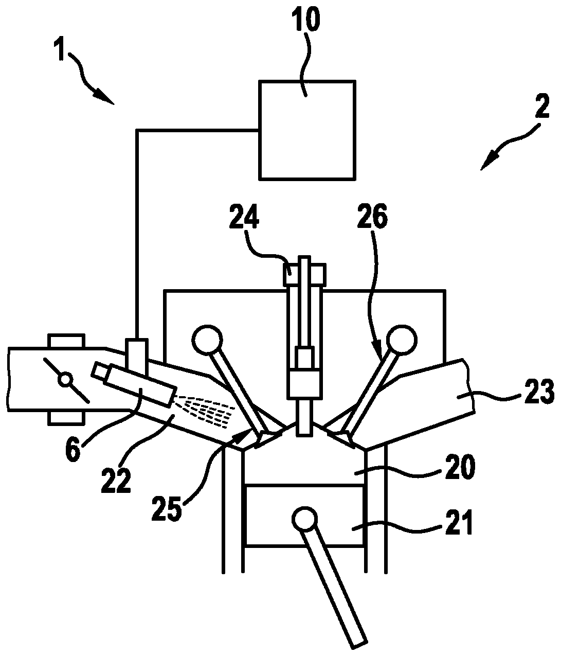
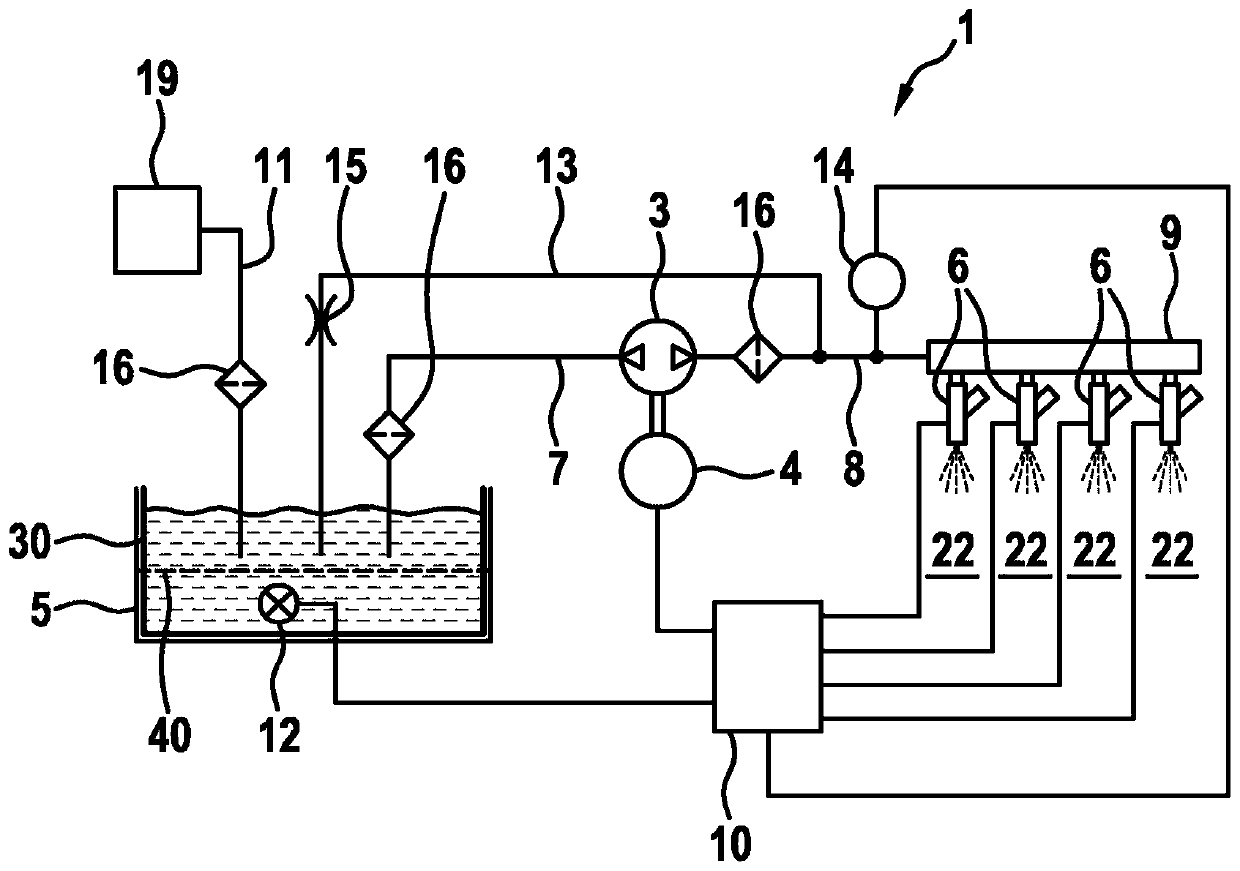
[0025] Refer below figure 1 and 2The device 1 for injecting water of the internal combustion engine 2 according to the first embodiment will be described in detail. The internal combustion engine 2 is operated in particular according to the Otto principle and with direct gasoline injection. Such an internal combustion engine is to be understood as an internal combustion engine in which the combustion of gasoline or a gasoline-air mixture is effected by ignition from an external source in the form of a spark plug. Since in such internal combustion engines the point of ignition is precisely predetermined by external ignition and the combustion is improved by water injection, a fail-safe operation of the internal combustion engine 2 is guaranteed by the use of cationic acid-forming metals and by the use of ultraviolet radiation for water purification Way.

[0026] exist figure 1 An internal combustion engine 2 is schematically shown in , which has a plurality of cylinders. E...


PUM


Abstract

The invention relates to a water injection device of an internal combustion engine (2), comprising at least one water tank (5) for storing water, at least one water injector (6) for injecting water, which water injector is connected to the water tank (5), and at least one conveying element (3) for conveying the water from the water tank (5) to the water injector (6), wherein, according to the invention, the device (1) comprises a metal that forms cationic acid, in particular silver, for decontaminating the water.

Description

technical field [0001] The invention relates to a device for injecting water of an internal combustion engine and to such an internal combustion engine. Another aspect of the invention relates to a method for spraying water by means of a water spray device according to the invention. Background technique [0002] Due to the increasing demands on reducing CO2 emissions, internal combustion engines are increasingly optimized with regard to fuel consumption. However, the known internal combustion engines cannot be operated optimally with regard to consumption at operating points with high loads, since the operation is limited by the tendency to knock and the high exhaust gas temperature. One possible measure for reducing the tendency to knock and for lowering the temperature of the exhaust gas is water injection. Here, a separate water injection system is usually present in order to be able to implement the water injection. Thus, a water injection system for an internal comb...

Claims


Application Information

Patent Timeline
IPC IPC(8): F02M25/028C02F1/50
CPCC02F1/001C02F1/32C02F1/505F02M25/028Y02T10/12
Inventor C·埃西希T·毛赫尔C-J·霍夫曼A·罗特
Owner ROBERT BOSCH GMBH
Why Eureka
Try Eureka