
Magnetically levitated rotor and a rotary machine with such a rotor

Inactive Publication Date: 2019-01-10
LEVITRONIX
View PDF7 Cites 4 Cited by
  • Summary
  • Abstract
  • Description
  • Claims
  • Application Information

AI Technical Summary

Benefits of technology

This patent describes a special coating for a rotor that prevents damage from acidic substances. The coating consists of a metallic layer and a fluoropolymer outer sheathing with parylene coating in between. The use of parylene coating is advantageous because it has high thermal stability. The combination of the coating and the sheathing provides better protection against gaseous and liquid components. The use of specific metallic layers (e.g. nickel, gold, or rhodium) makes the coating highly effective against acidic substances. The sheathing can be made of perfluoroalkoxy polymer, ethylene chlorotrifluoroethylene, or polyvinylidene fluoride, which can be easily processed. The addition of a heat protection film between the plastic coating and the sheathing can further enhance the protection against temperature damage.

Problems solved by technology

The materials typically used for permanent magnets, such as neodyne, samarium or cobalt for example, generally have a very low resistance to such aggressive substances.
However, the fluorinated hydrocarbons very often do not form a sufficient barrier to gaseous components of the chemicals.
Furthermore, investigations have shown that corrosion occurs even with such sheathings of fluorinated hydrocarbons after relatively short operating times, in particular on the permanent magnets of the rotor.
This can result in inflation of the rotor, in degradation of the metallic coating, in chipping off parts of the rotor core or of the sheathing up to a complete destruction of the magnetically effective core of the rotor.
This problem is complicated by the fact that the sheathing of metal must be relatively close to the permanent magnet, because the magnetic air gap cannot be increased during a magnetic levitating without a high loss of force.
In addition, ozone, hydrogen or acid vapors can diffuse through the plastic and attack the metallic sheathing.
Once the metallic sheathing of the rotor has been attacked, metal ions can diffuse through the plastic sheathing into the fluid to be conveyed and contaminate the fluid.
In applications in the semiconductor industry, such metal ions in the fluid can have extremely negative consequences, because, for example, even very low concentrations of the dissolved metal ions can change the doping of the semiconductor structures to be treated in an uncontrolled manner and, in the worst case, make the semiconductor products unusable.
But even galvanically applied metallic sheathings, for example using gold or rhodium, which are considered extremely inert, have surprisingly not led to really satisfactory results.
After a relatively short service life of 100-200 hours, for example, massive corrosion can occur on the rotor.

Method used


Image

  • Magnetically levitated rotor and a rotary machine with such a rotor
  • Magnetically levitated rotor and a rotary machine with such a rotor
  • Magnetically levitated rotor and a rotary machine with such a rotor

Examples


first embodiment

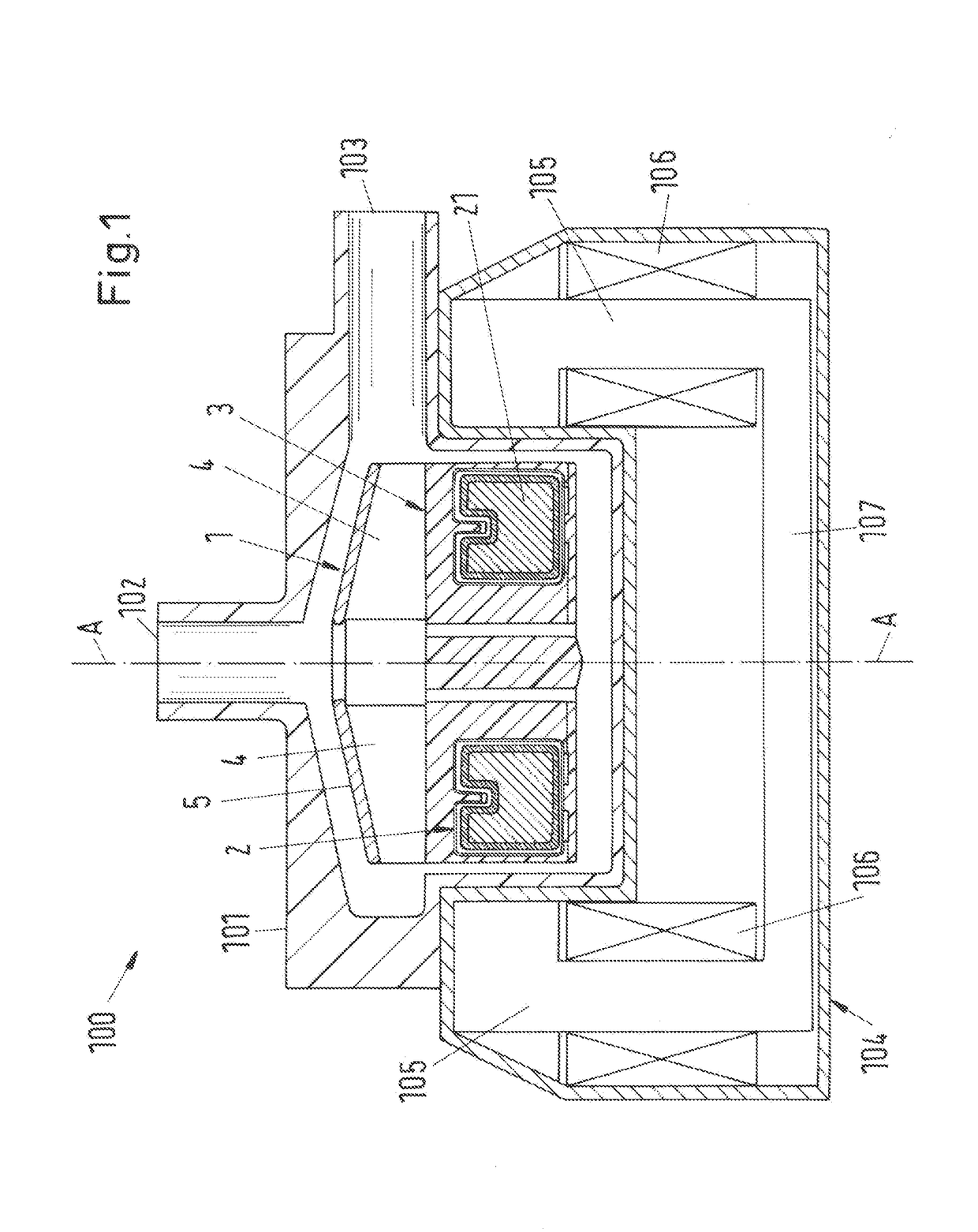
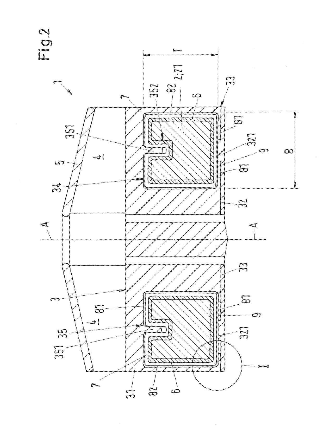
[0055]The centrifugal pump 100 comprises a pump housing 101 with an inlet 102 and an outlet 103 for the fluid to be conveyed. a rotor that can be magnetically levitated according to the invention is disposed in the pump housing 101, which rotor is referred to as a whole with the reference sign 1. For a better understanding, FIG. 2 shows a sectional view of the rotor 1 that can be magnetically levitated of FIG. 1. Rotor 1 has a magnetically effective core 2, which comprises at least one permanent magnet 21, to drive the rotation of the rotor 1 about a set rotation axis, which defines an axial direction A. A direction perpendicular to the axial direction A is described as the radial direction.

[0056]In the first embodiment, the magnetically effective core 2 includes only the permanent magnet 21, which here is designed as a ring-shaped permanent magnet 21. Preferably the ring-shaped permanent magnet 21 is in one piece. However, it is also possible that the permanent magnet 21 comprises ...

second embodiment

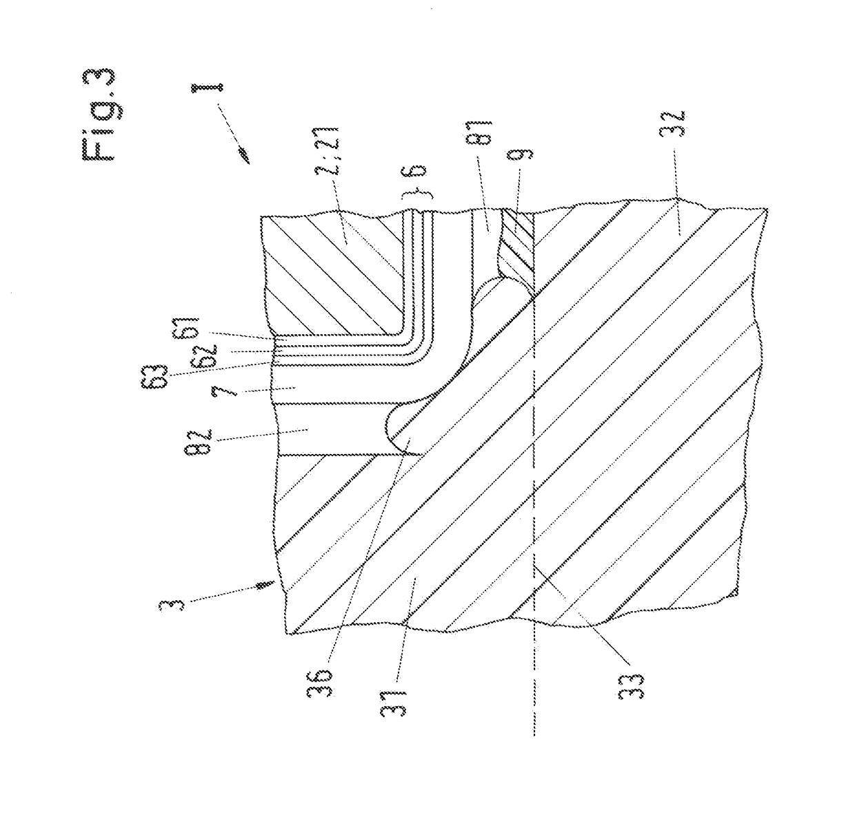
[0098]According to the invention, also in the rotor 1 according to the invention, the sheathing 3 includes a thermoplastically processible, in particular a weldable, fluoropolymer, which completely encloses the magnetically effective core 2. Furthermore, each permanent magnet 21 has the metallic coating 6, and the plastic coating 7 is provided between the metallic coating 6 and the sheathing 3, which plastic coating in turn includes a polymer belonging to the parylene family.

[0099]Also in the second embodiment of the rotor 1, the sheathing 3 preferably includes the weldable PFA. Alternatively, it is preferred if the sheathing 3 is made of ECTFE or PVDF.

[0100]In the second embodiment, the pump housing 101 preferably also includes a fluoropolymer, however, it does not have to be weldable or thermoplastically processible. Of course, it is also possible that the pump housing 101 includes the same plastic or polymer as the coating.

[0101]With regard to the design of the metallic coating 6...


PUM

PropertyMeasurementUnit
Metallic bondaaaaaaaaaa

Abstract

A magnetically levitated rotor includes a magnetically effective core and a sheathing made of a thermoplastically processible fluoropolymer. The sheathing completely encloses the magnetically effective core. The magnetically effective core comprises at least one permanent magnet and each permanent magnet has a metallic coating for protection against acidic or chemically aggressive substances. A plastic coating is disposed between the metallic coating and the sheathing, and includes a polymer belonging to the family of parylenes.

Description

CROSS-REFERENCE TO RELATED APPLICATION[0001]This application claims priority to European Application No. 17179501.6, filed Jul. 4, 2017, the contents of which are hereby incorporated herein by reference.BACKGROUNDField of the Invention[0002]The invention relates to a rotor for a rotary machine with a magnetically levitated rotor.Background of the Invention[0003]Rotary machines with magnetically levitated rotors, for example centrifugal pumps or mixing devices or stirring devices are used in many technical fields, in particular for applications in which highly pure fluids are conveyed, stirred or mixed, without the fluids being contaminated by abrasion particles from mechanical bearings. In the semiconductor industry, for example, magnetically levitated rotors are used for conveying ultrapure water as well as acidic, oxidizing or otherwise chemically aggressive fluids, as they are used in the semiconductor industry for the production or processing of semiconductor structures. It is c...

Claims


Application Information

Patent Timeline
IPC IPC(8): H02N15/00H02K1/04H02K1/27H02K1/28F04D13/06F04D7/06
CPCH02N15/00H02K1/04F04D7/06H02K1/28F04D13/0653H02K1/2733H02K1/02H02K1/22H02K1/2706H02K5/02H02K15/03H02K1/278F05D2300/43F05D2300/142F04D25/0633F04D13/06F04D13/064F04D13/0666F04D25/06F04D29/023F04D29/026F04D29/048F04D29/2205H01F41/026H02K3/44H02K7/09H02K7/14F05D2300/1435F05D2300/16H02K5/128H02K1/27H02K1/276
Inventor BARLETTA, NATALEFOIERA, GIAMPIEROEBERLE, THOMASSCHOB, RETOGEMPP, THOMASHOFFMANN, MATHIAS
Owner LEVITRONIX
Learn More