

Self-test method and device
A technology of geographic location information and robots, which is applied in the field of self-inspection methods and devices, and can solve problems such as not being able to know the movement capabilities of robots in time
- Summary
- Abstract
- Description
- Claims
- Application Information
AI Technical Summary
Problems solved by technology
Method used
Image

Examples
Embodiment 1
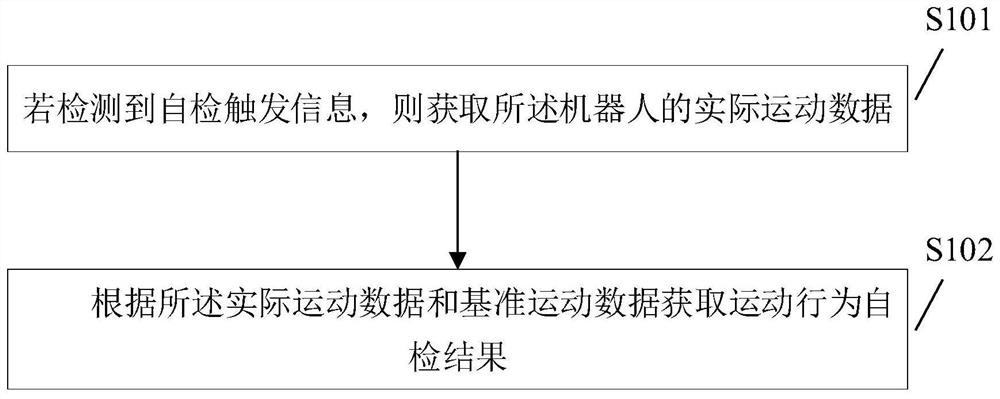
[0044] figure 1 It shows a schematic flow chart of the first self-inspection method provided by the embodiment of the present application. The self-inspection method is applied to a robot, and the details are as follows:
[0045] Step S101, if the self-test trigger information is detected, the actual motion data of the robot is acquired.
[0046] Specifically, if the self-inspection trigger information is detected by the specified device, the actual movement data of the robot is obtained through the self-inspection program. Wherein, the self-test trigger information is used to trigger (start) the self-test program.
[0047] As an example and not limitation, the specified device may include any one of the following: camera, laser radar. The self-check trigger information includes, but is not limited to, any of the following: specified two-dimensional image information, specified three-dimensional item information. When the designated device is a camera, correspondingly, the ...
Embodiment 2
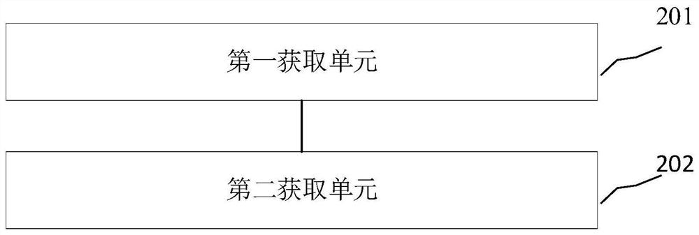
[0073] Corresponding to the first embodiment above, figure 2A schematic structural diagram of a self-inspection device provided by an embodiment of the present application is shown. The self-inspection device is applied to a robot. For convenience of description, only parts related to the embodiment of the present application are shown.
[0074] The self-checking device includes: a first acquisition unit 201 and a second acquisition unit 202 .
[0075] The first acquisition unit 201 is configured to acquire the actual motion data of the robot if self-test trigger information is detected;
[0076] Optionally, since the robot often needs to perform tasks, if the execution process of the specified task and the execution process of the self-inspection method are independent of each other, it will have a negative impact on the self-inspection efficiency or task execution efficiency, for example, If the specified task is executed first, and then the self-inspection method is execu...
Embodiment 3
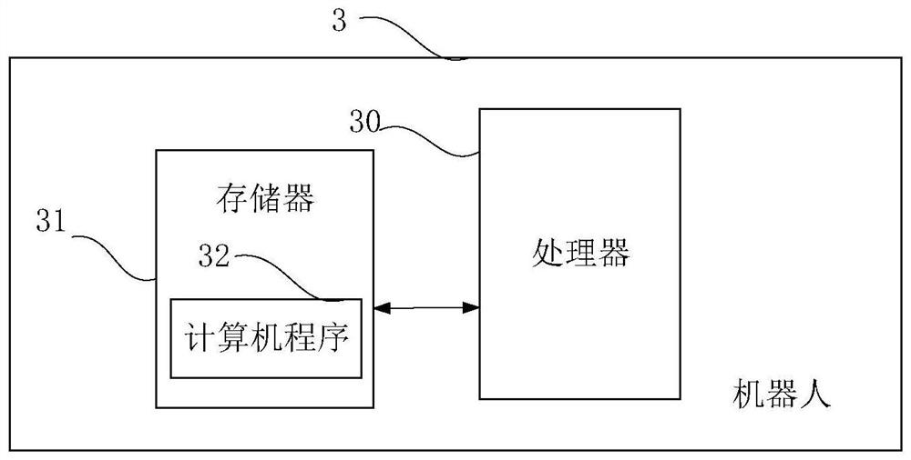
[0090] image 3 It is a schematic structural diagram of a robot provided by an embodiment of the present application. Such as image 3 As shown, the robot 3 of this embodiment includes: at least one processor 30 ( image 3 Only one is shown in ), a processor, a memory 31 and a computer program 32 stored in the memory 31 and operable on the at least one processor 30. When the processor 30 executes the computer program 32, the above-mentioned Steps in any of the embodiments of the self-inspection method.
[0091] The robot may include, but not limited to, a processor 30 and a memory 31 . Those skilled in the art can understand that, image 3 It is only an example of the robot 3, and does not constitute a limitation to the robot 3. It may include more or less components than shown in the figure, or combine some components, or different components. For example, it may also include input and output devices, network interfaces, etc. into the device, etc.
[0092] The so-called...
PUM
 Abstract
Description
Claims
Application Information