Supercharge Your Innovation With Domain-Expert AI Agents!

Cooperating pressing and clamping device for automotive electronic parts processing

A technology of clamping device and electronic parts, which is applied in the direction of workpiece clamping device, metal processing, metal processing equipment, etc., can solve the problems of lack of electric screwdriver positioning and installation structure, low efficiency of locking and installation, and high labor intensity of both hands, etc., to achieve Eliminates the trouble of manual moving and reset, simple and quick to use, and convenient through-tightening effect

Active Publication Date: 2021-08-24
蒙城县十速信息科技有限公司
View PDF10 Cites 0 Cited by
  • Summary
  • Abstract
  • Description
  • Claims
  • Application Information

AI Technical Summary

Problems solved by technology

[0004] The purpose of the present invention is to provide a matching pressing and clamping device for the processing of automotive electronic parts, so as to solve the above-mentioned background technology that cannot be well used for clamping horns with different sizes and specifications. The positioning installation structure requires frequent hand-holding, moving, lifting and releasing the electric screwdriver during screwing, which is cumbersome to operate and use. In addition, the power board is mostly used for hand-held loading and needs to be calibrated with eyes, which may cause eye fatigue. In addition, the left-hand hand is used to connect the power The locking operation method of holding an electric screwdriver in the right hand will also cause high labor intensity for both hands and low efficiency of locking and installation.

Method used


Image

  • Cooperating pressing and clamping device for automotive electronic parts processing
  • Cooperating pressing and clamping device for automotive electronic parts processing
  • Cooperating pressing and clamping device for automotive electronic parts processing

Examples


Embodiment Construction

[0031] The following will clearly and completely describe the technical solutions in the embodiments of the present invention with reference to the accompanying drawings in the embodiments of the present invention. Obviously, the described embodiments are only some, not all, embodiments of the present invention.

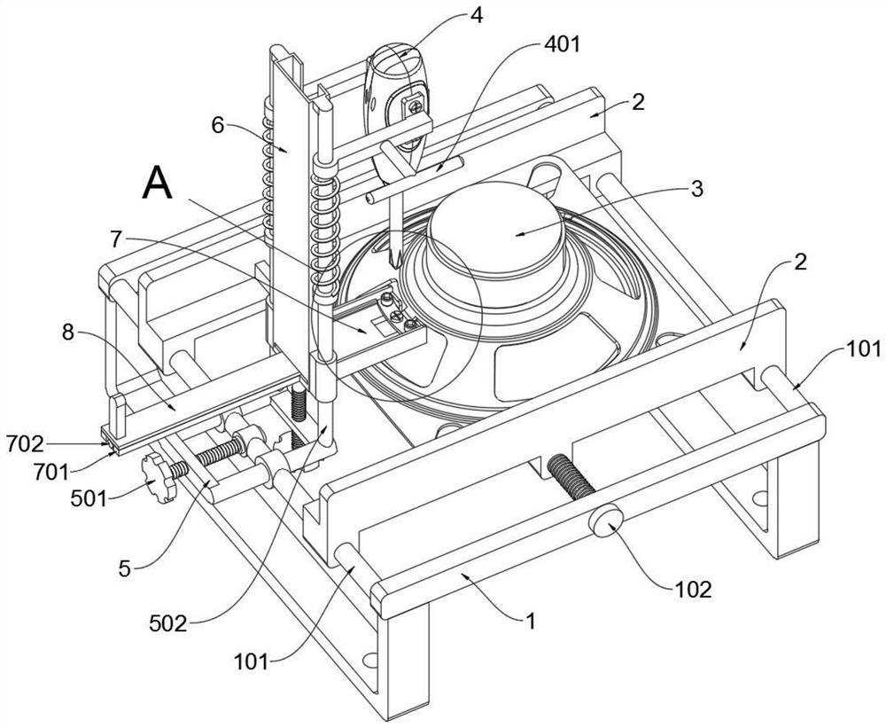
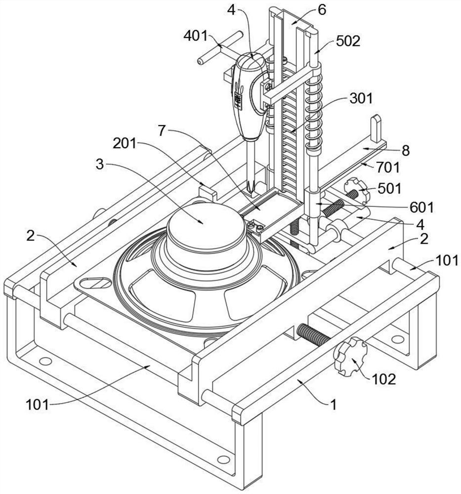
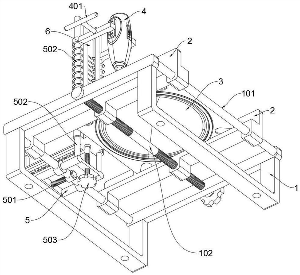
[0032] see Figure 1 to Figure 10 , an embodiment provided by the present invention: a cooperative press clamping device for processing automotive electronic parts, including a support frame 1, a horn 3, an electric screwdriver 4, a positioning frame 5, a feeding trough 6 and a feeding push plate 8; The support frame 1 includes a positioning shaft 101 and a double-ended threaded rod 102. The left and right ends of the two front and rear cross braces on the top of the support frame 1 are symmetrically supported and welded with two positioning shafts 101, and the two L-shaped splints 2 are front and rear. Corresponding sliding sleeves are set on the two positioning sha...


PUM


Abstract

The invention discloses a matching pressing and clamping device for the processing of automotive electronic parts, relates to the field of supporting equipment for the processing of automotive electronic components, and solves the problem of the existing clamping device. Most of the electric boards use hand-held feeding and need to be calibrated easily. It causes eye fatigue and low efficiency of locking installation. A cooperative pressing and clamping device for the processing of automotive electronic parts, including a positioning frame, a feeding chute and a feeding push plate; the supporting frame includes a positioning shaft and a double-ended threaded rod, and two front and rear cross braces at the top of the supporting frame The left and right ends of the plate are symmetrically supported and welded with two positioning shafts, and the two L-shaped splints are set on the two positioning shafts in the form of front and rear corresponding sliding sleeves; the middle of the two front and rear cross braces on the top of the support frame There is a double-ended threaded rod installed on the segment. The inner walls on both sides of the feeding trough and the two baffles of the present invention can block the positioning electric connection board to prevent it from following the electric screwdriver to rotate and shift, which saves the trouble of pinching the positioning electric connection board by hand.

Description

technical field [0001] The invention relates to the technical field of supporting equipment for processing electronic components of automobiles, in particular to a matching pressing and clamping device for processing electronic components of automobiles. Background technique [0002] At present, with the rapid development of the automobile industry, the number of automobiles has reached an unprecedented scale, and people's requirements for automobiles are getting higher and higher. The horn is an essential electronic room for a car. It is an audio signal device. During the driving process of the car, the driver sends out the necessary sound signal according to the needs and regulations to warn pedestrians and attract the attention of other vehicles to ensure traffic safety. For reminders and transmission of signals. [0003] In the process of car horn processing, the wiring board needs to be screwed to the horn body, which requires a pressing and clamping device to position...

Claims


Application Information

Patent Timeline
Patent Type & Authority Patents(China)
IPC IPC(8): B23P19/06B23P19/00B25B11/02
CPCB23P19/00B23P19/001B23P19/06B25B11/02
Inventor 解钟敏
Owner 蒙城县十速信息科技有限公司
Features
  • R&D
  • Intellectual Property
  • Life Sciences
  • Materials
  • Tech Scout
  • Unparalleled Data Quality
  • Higher Quality Content
  • 60% Fewer Hallucinations
Learn More