

Image superposition method and device, and electronic equipment
A superposition method and image technology, applied in the field of image processing, can solve problems such as consumption, complex processing process, and multiple CPU computing resources.
- Summary
- Abstract
- Description
- Claims
- Application Information
AI Technical Summary
Problems solved by technology
Method used
Image

Examples
Embodiment Construction
[0034] In order to make the object, technical solution and advantages of the present invention clearer, the present invention will be described in further detail below in conjunction with specific embodiments and with reference to the accompanying drawings.
[0035] It should be noted that all expressions using "first" and "second" in the embodiments of the present invention are to distinguish two entities with the same name but different parameters or parameters that are not the same, see "first" and "second" It is only for the convenience of expression, and should not be construed as a limitation on the embodiments of the present invention, which will not be described one by one in the subsequent embodiments.
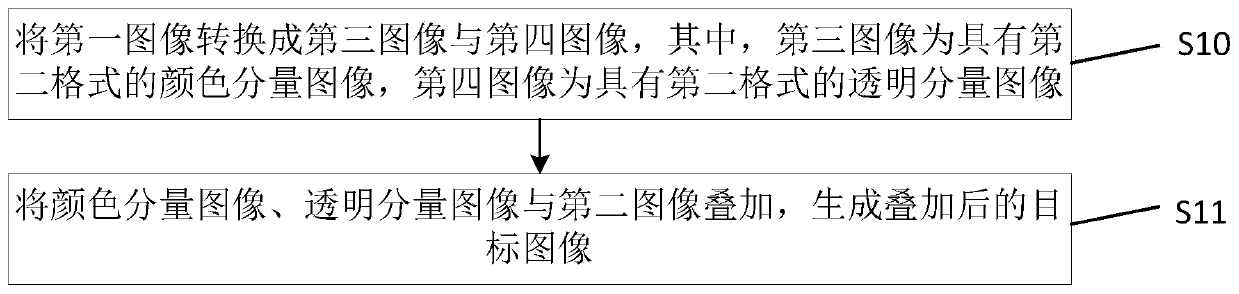
[0036] figure 1 It is a schematic flow chart of the method of the embodiment of the present invention. As shown in the figure, the image overlay method provided by the embodiment of the present invention is used to overlay the first image and the second image, wherei...
PUM
 Abstract
Description
Claims
Application Information