An optical axis consistency adjustment device

A technology of adjustment device and consistency, applied in the direction of measurement device, optical radiation measurement, instrument, etc., can solve the problem of inconvenient adjustment and testing, and achieve the effect of reducing the problem of inconsistency

Active Publication Date: 2022-03-25
广州市长岛光电机械厂
View PDF12 Cites 0 Cited by
  • Summary
  • Abstract
  • Description
  • Claims
  • Application Information

AI Technical Summary

Problems solved by technology

[0003] An optical axis adjustment device is provided to solve the extremely inconvenient problem of adjusting and testing the inner field and the outer field

Method used


Image

  • An optical axis consistency adjustment device
  • An optical axis consistency adjustment device

Examples


Embodiment 1

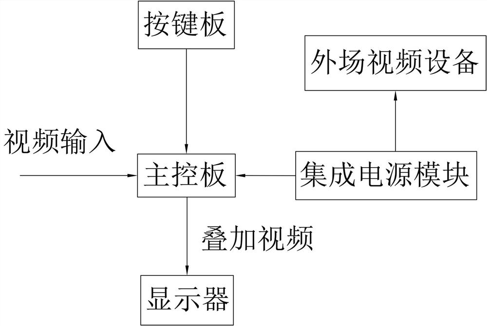
[0018] The optical axis adjustment device of this embodiment is mainly composed of an independent power supply, a main control board, a display, and a key board;

[0019] to combine figure 1 and figure 2 as shown,

[0020] The independent power supply is used to power the infrared thermal imager, visible light components, laser emitting device and laser receiving device;

[0021] The display is used for intuitive observation and combined with the key board to adjust the consistency of the optical axis;

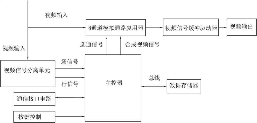
[0022] The main control board includes: video signal separation module, communication interface circuit, main controller, 8-channel analog multiplexer, video signal buffer driver, data memory; the main control board is used to process video signals, including infrared heat Imager, visible light components, and laser receiving device for imaging signal processing;

[0023] The video signal separation module described herein separates the video signals received by the infra...


PUM


Abstract

The invention belongs to the technical field of video signal processing, relates to video overlay technology, and in particular to an optical axis consistency adjustment device. The invention discloses an optical axis consistency adjustment device, which comprises an independent power supply, a main control board, a display, and a key board. The beneficial effect of the present invention is that: on the basis of the original infield debugging equipment, an optical axis consistency adjustment device in the outfield is added. In this way, the inconsistency between infield and outfield debugging is greatly reduced, and the adjustment test problem can be completed at one time in the outfield, and then the debugging results can be confirmed through the infield environment test. Therefore, through an adjustment device based on video signal superposition processing, the optical axis consistency of the equipment can be adjusted without the original industrial computer system.

Description

technical field [0001] The invention relates to video overlay technology, in particular to an optical axis consistency adjustment device. Background technique [0002] In the development process of photoelectric systems, it is often necessary to conduct various evaluations and tests on the internal performance of the physical prototype of photoelectric detection products. In the photoelectric equipment, the center of the field of view of the infrared camera, TV component (or physical optics) and the laser emission axis and receiving axis must be calibrated, that is, the calibration of the three axes is parallel and consistent. It is also necessary to ensure the consistency of the optical axis. The calibration of all these optical axes needs to be based on the scale line in the visible window as a reference to achieve accurate calibration. The implementation method on the active equipment is to digitize the video signal of the component first, and then realize cross superpos...

Claims


Application Information

Patent Timeline
Patent Type & Authority Patents(China)
IPC IPC(8): H04N5/265H04N5/445G01J5/80
CPCH04N5/265H04N5/445G01J5/10G01J2005/0077G01J5/80
Inventor 彭钧陶庄军曾涛张奕耿邓关平
Owner 广州市长岛光电机械厂
Why Eureka
Try Eureka