A multi-channel signal superposition device

A multi-channel signal and optical signal technology, applied in the field of optoelectronics, can solve the problems of easy crosstalk of signals and complex structure of signal synthesis devices, etc., and achieve the effects of not easy crosstalk, large absorption peak span and small volume

Active Publication Date: 2018-05-29
TSINGHUA UNIV
View PDF7 Cites 0 Cited by
  • Summary
  • Abstract
  • Description
  • Claims
  • Application Information

AI Technical Summary

Problems solved by technology

[0004] For this reason, the existing signal synthesizing device to be solved by the present invention is complex in structure, easy to cause crosstalk of signals, and unable to realize superimposition of different potential signals, thereby providing a multi-channel signal with simple structure, stable signal, and superimposition of different potential signals Superposition device

Method used


Image

  • A multi-channel signal superposition device
  • A multi-channel signal superposition device
  • A multi-channel signal superposition device

Examples


Embodiment

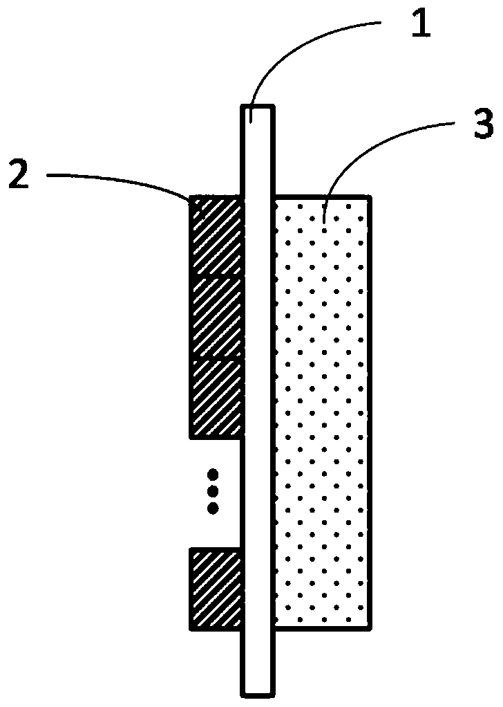
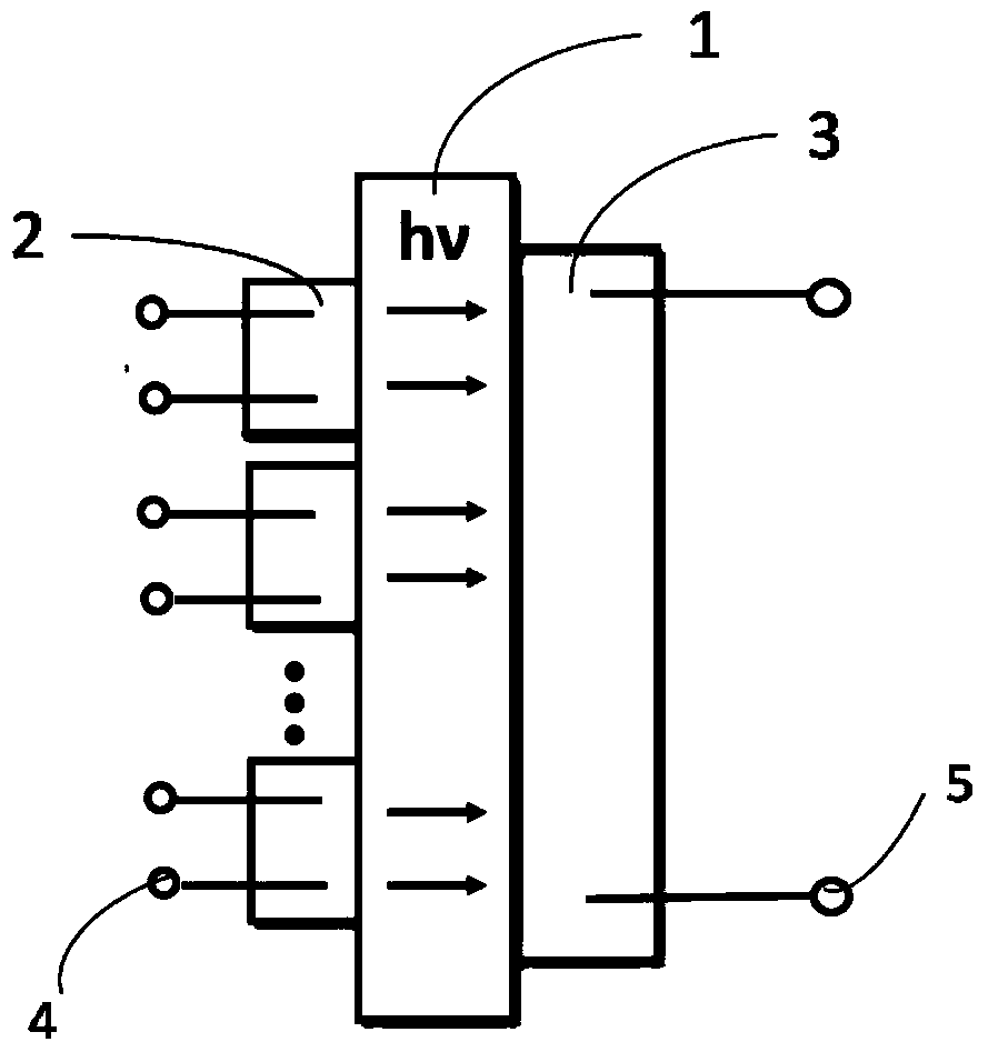
[0048] This embodiment provides a multi-channel signal superposition device, such as figure 1 As shown, it includes a transparent electrically insulating substrate 1, a plurality of electroluminescent components 2 and a photosensitive component 3 respectively arranged on both sides of the substrate 1, and the orthographic projection of each of the electroluminescent components 2 on the substrate 1 Within the range of the orthographic projection of the photosensitive component 3 on the substrate 1 , the light emitting surface of the electroluminescent component 2 and the sensing surface of the photosensitive component 3 are both arranged close to the substrate 1 .

[0049] It should be understood that, according to common knowledge in the art, the “both sides” of the substrate 1 should be the surface with the largest area and the opposite surface of the substrate 1 .

[0050] As a changeable embodiment of the present invention, the multi-channel signal superimposing device may ...


PUM


Abstract

A multi-channel signal superposition device according to the present invention includes a photosensitive component and several electroluminescent components arranged on the sensing surface of the photosensitive component, and the light-emitting surface of the electroluminescent component is connected to the photosensitive component. The sensing surface is stacked or set close to each other; each current signal is converted into an optical signal by each electroluminescent component, and then the optical signal is superimposed and converted by the photosensitive component on the other side of the substrate, and output as a single current signal . Since the single-channel current signal is converted into an optical signal through the electroluminescent device, and then converted into a single current signal by superimposing the optical signal through the photosensitive component, the signal is not easy to crosstalk, has high stability, and can realize signals at different potentials. The superposition between them has a wide range of applications.

Description

technical field [0001] The invention relates to the field of optoelectronics, in particular to a multi-channel current signal superposition device capable of superimposing different potential signals. Background technique [0002] Signal modulation technology is of great significance in the fields of video and audio transmission, wireless communication acquisition, system control, etc. With the rapid development of optical fiber sensing technology and optical fiber communication network technology, using signal modulation technology to control the current of semiconductor devices has become Become the current research direction and trend in this field. Modulation technology can make the modulated signal have strong anti-interference ability, and at the same time, it has little interference to adjacent channel signals, convenient demodulation and easy integration. Signal superposition is the basis of signal modulation technology. For example, in terms of video transmission, ...

Claims


Application Information

Patent Timeline
Patent Type & Authority Patents(China)
IPC IPC(8): H03K3/02
Inventor 董桂芳李文海李东邱勇
Owner TSINGHUA UNIV
Why Eureka
Try Eureka