Novel wiring harness connector

A wire harness, a new type of technology, applied in the field of wire harnesses, can solve the problems of unlayered wire binding, disordered order, interference, etc., and achieve the effects of avoiding crosstalk between wires, protecting wire harnesses, and facilitating maintenance

Inactive Publication Date: 2018-11-27
YANGZHOU MINGYU WIRE & CABLE CO LTD
View PDF0 Cites 0 Cited by
  • Summary
  • Abstract
  • Description
  • Claims
  • Application Information

AI Technical Summary

Problems solved by technology

[0002] With the development of science and technology, there are more and more electronic products, and there are more and more circuits inside electronic products. Therefore, it is often necessary to organize the circuits inside electronic products. The existing wire harness generally includes a wire harness The main body is provided with an array of wire harness holes on the main body of the wire harness. By passing cables and other wires through the wire harness holes respectively, the arrangement of the cables and wires can be realized, and the winding and knotting of multiple cables can be avoided. In some wire harness devices, the internal wires of existing electronic products are tied to wire winding needles, square plates, brackets and other components by cable ties or winding ropes. Generally, the space is limited, and the passing wires are all tied into one or more bundles. This solution causes the wires to be tied without layers, the order is chaotic and complicated, and there is a risk of interference. During maintenance, if there is a problem with one wire, the entire string needs to be removed, which is more complicated, which is far from satisfying the current people. The requirements for this product, so how to design a new type of wire harness has become a problem we are currently trying to solve

Method used


Image

  • Novel wiring harness connector
  • Novel wiring harness connector
  • Novel wiring harness connector

Examples


Embodiment Construction

[0017] The present invention will be further described below in conjunction with specific embodiments, wherein, the accompanying drawings are only for exemplary illustrations, and what is shown is only a schematic diagram, rather than a physical map, and cannot be understood as a limitation to this patent. In order to better illustrate the present invention Specific embodiments, some parts in the drawings will be omitted, enlarged or reduced, and do not represent the size of the actual product. For those skilled in the art, it is understandable that some known structures and their descriptions in the drawings may be omitted. Based on The specific implementation modes in the present invention and all other specific implementation modes obtained by persons of ordinary skill in the art without making creative efforts all belong to the protection scope of the present invention.

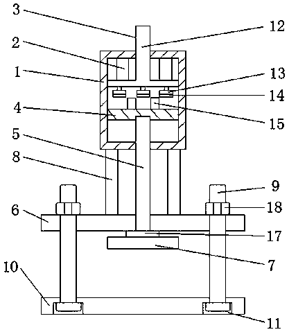
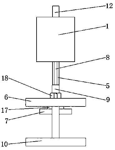
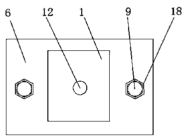
[0018] see Figure 1-Figure 3 , the present invention provides a technical solution: a new type of wir...


PUM


Abstract

The invention discloses a novel wiring harness connector. The novel wiring harness connector comprises a framework, wherein extension springs are symmetrically fixed on the top of the inner cavity ofthe framework; the bottom ends of the extension springs are connected with pushing parts; the top ends of the pushing parts penetrate through the framework; the inner cavity of the framework is provided with a pushing plate which is positioned below the pushing parts; the bottom of the pushing plate is connected with a pushing rod; one end of the pushing rod penetrates through the bottom of the framework, the other end of the pushing rod penetrates through a connecting plate, the bottom end of the pushing rod is fixedly connected with a pushing rod plate, the bottom of the framework is symmetrically provided with dampers; the dampers are positioned between the framework and the connecting plate; the connecting plate is provided with a bottom plate through symmetrical screws; and the bottomof the bottom plate is symmetrically provided with screw limiting holes. The novel wiring harness connector realizes collection or distribution of wiring harnesses, and protects the wiring harnesses,so that the wiring harness fixing effect can be realized, and the collection or distribution of the wiring harnesses can be freely regulated; and moreover, the novel wiring harness connector is convenient to dismount, is attractive, and has a wide application prospect.

Description

technical field [0001] The invention relates to the technical field of wire harnesses, in particular to a novel wire harness. Background technique [0002] With the development of science and technology, there are more and more electronic products, and there are more and more circuits inside electronic products. Therefore, it is often necessary to organize the circuits inside electronic products. The existing wire harness generally includes a wire harness The main body is provided with an array of wire harness holes on the main body of the wire harness. By passing cables and other wires through the wire harness holes respectively, the arrangement of the cables and wires can be realized, and the winding and knotting of multiple cables can be avoided. In some wire harness devices, the internal wires of existing electronic products are tied to wire winding needles, square plates, brackets and other components by cable ties or winding ropes. Generally, the space is limited, and ...

Claims


Application Information

Patent Timeline
Patent Type & Authority Applications(China)
IPC IPC(8): H02G3/02
CPCH02G3/02
Inventor 刘慧萍陈学厚王冬
Owner YANGZHOU MINGYU WIRE & CABLE CO LTD
Why Eureka
Try Eureka