Cyclonic array such as for a vacuum cleaner

a cyclonic array and vacuum cleaner technology, applied in the direction of filter regeneration, dispersed particle filtration, using liquid separation agents, etc., can solve the problem of re-entering dirt and separation dirt, and achieve the effect of convenient cleaning or repair, easy assembly and disassembly

Inactive Publication Date: 2011-01-11
OMACHRON INTPROP
View PDF25 Cites 128 Cited by
  • Summary
  • Abstract
  • Description
  • Claims
  • Application Information

AI Technical Summary

Benefits of technology

[0005]An advantage of the construction is that a cyclone unit comprising a plurality of cyclones in parallel is easily and reliably manufactured. Preferably, each cyclone chamber has its own dirt collection chamber. Accordingly, no cross flow between adjacent cyclones is permitted via the dirt outlet of the cyclones due to varying backpressure at the cyclone inlets. This cross flow could result in separated dirt being re-entrained.
[0008]Embodiments in accordance with this broad aspect may be advantageous because the cyclonic cleaning unit may be manufactured from only three molded pieces. Accordingly, the cyclonic cleaning unit may be relatively easy to assemble and disassemble, and therefore relatively easy to clean or repair.

Problems solved by technology

This cross flow could result in separated dirt being re-entrained.

Method used


Image

  • Cyclonic array such as for a vacuum cleaner
  • Cyclonic array such as for a vacuum cleaner
  • Cyclonic array such as for a vacuum cleaner

Examples


Embodiment Construction

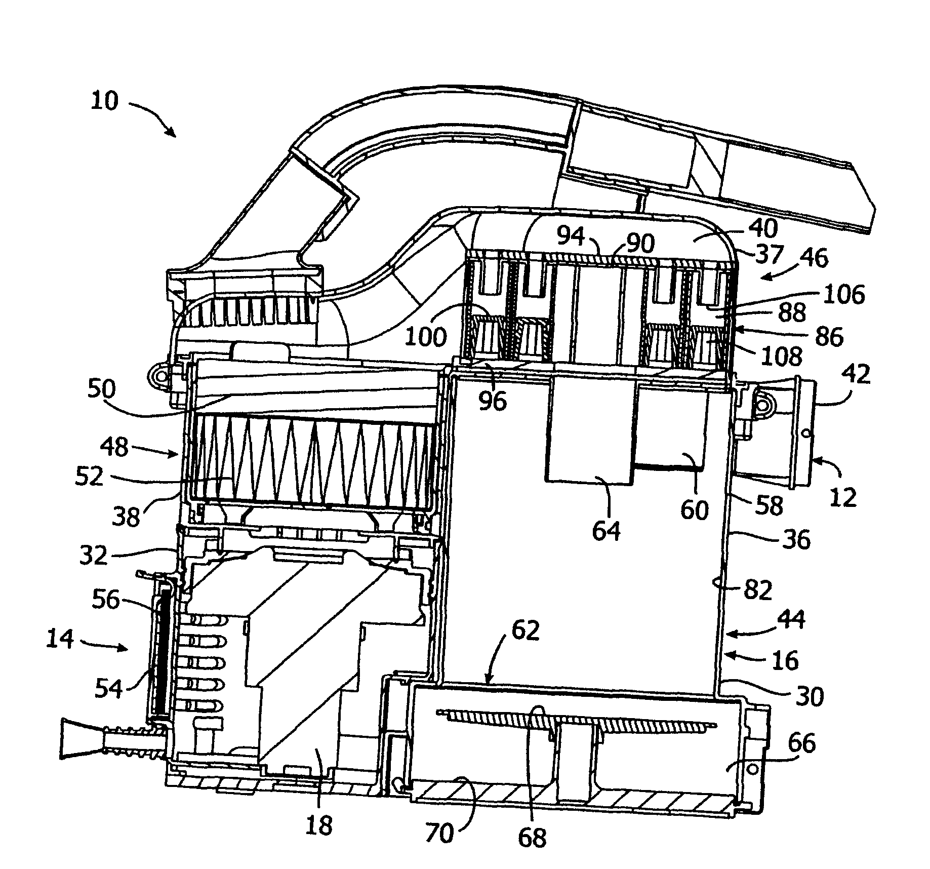
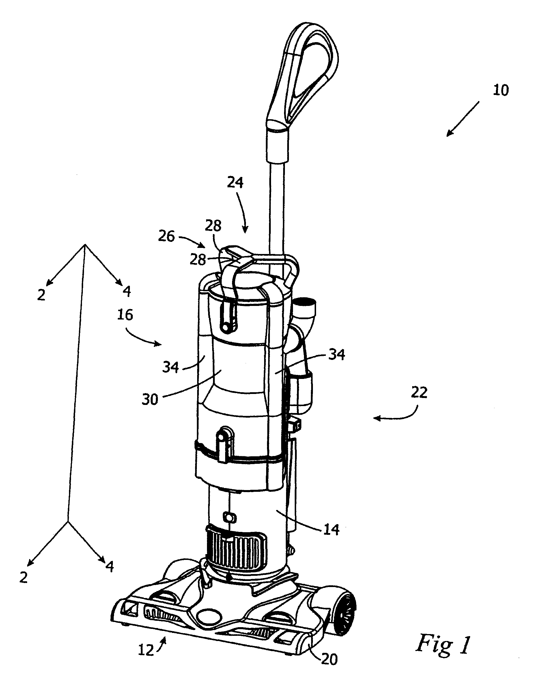
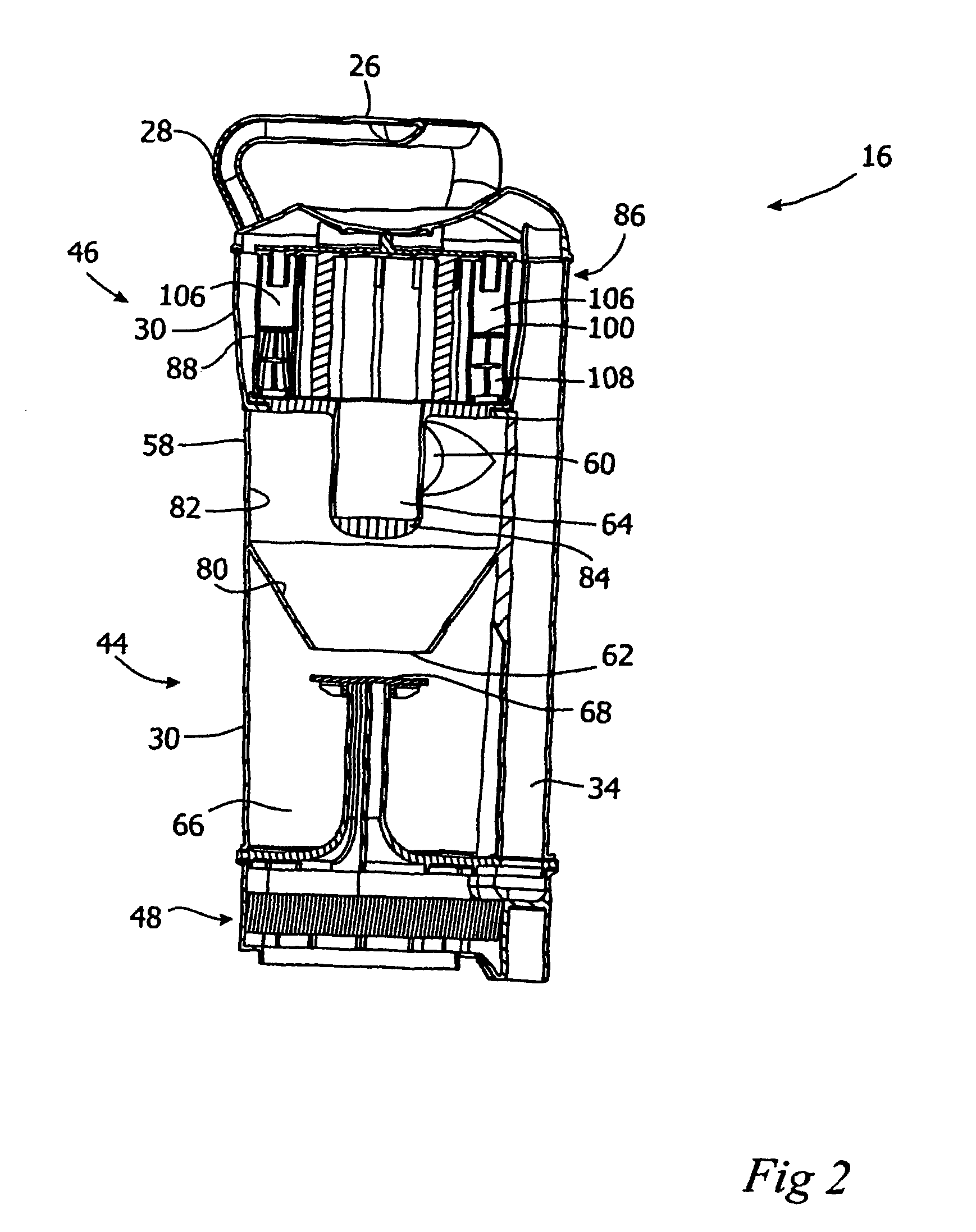
[0045]Embodiments of a surface cleaning apparatus 10 of the present invention are shown in FIGS. 1 and 5-6. As shown in FIG. 1, the surface cleaning apparatus 10 may be an upright vacuum cleaner. As shown in FIGS. 5 and 6, the surface cleaning apparatus 10 may be a wheel-mounted vacuum cleaner, which may be converted to a carryable vacuum cleaner. In other embodiments, the surface cleaning apparatus 10 may be another type of surface cleaning apparatus for example a canister type vacuum cleaner, a stick vacuum cleaner, a back pack vacuum cleaner, a hand-carryable vacuum cleaner, a carpet extractor or the like.

[0046]Surface cleaning apparatus 10 comprises a fluid flow path extending from a dirty fluid inlet 12 to a clean air outlet 14. A filtration unit 16 comprising at least one cyclonic cleaning stage is provided in the fluid flow path. A motor 18 is provided in the fluid flow path, for drawing fluid through the fluid flow path from the dirty fluid inlet 21 to the clean air outlet 1...


PUM

PropertyMeasurementUnit
open volumeaaaaaaaaaa
timeaaaaaaaaaa
flexibleaaaaaaaaaa

Abstract

A cyclonic cleaning stage for a, e.g., surface cleaning apparatus is provided. The cyclonic cleaning stage comprises a plurality of cyclones, which are integrally molded as a single body. Each cyclone has a cyclone body having an upper end, a lower end, a cyclone inlet, and a cyclone outlet. Each cyclone inlet has a top. A separately molded upper cover is mounted to the top of the single body at the upper ends. A separately molded lower cover is mounted on the single body at the lower ends of the cyclones.

Description

CROSS REFERENCES TO RELATED APPLICATIONS[0001]This application claims priority from U.S. Provisional Patent Applications 60 / 870,175 (filed Dec. 15, 2006), 60 / 884,767, filed on Jan. 12, 2007, and 60 / 889,014, filed on Feb. 9, 2007, each of which is incorporated herein by reference in their entirety.FIELD OF THE INVENTION[0002]This invention relates to a construction for a cyclonic array for use in, for example, a surface cleaning apparatus, such as vacuum cleaners, wet / dry vacuum cleaners and carpet extractors.BACKGROUND OF THE INVENTION[0003]Various different constructions for a surface cleaning apparatus are known in the art. Recently, vacuum cleaners have been designed which use one, and in some cases, two cyclonic cleaning stages. In particular, vacuum cleaners have been constructed which comprise a single first stage cyclone and a plurality of second stage cyclones in parallel.SUMMARY OF THE INVENTION[0004]In accordance with of this invention, a construction of a cyclone array is...

Claims


Application Information

Patent Timeline
Patent Type & Authority Patents(United States)
IPC IPC(8): B01D45/12
CPCA47L9/1608A47L9/1625A47L9/1641A47L9/1683B04C5/08B04C5/28Y10S55/03A47L9/16B04C5/185B08B5/00B08B13/00
Inventor CONRAD, WAYNE ERNEST
Owner OMACHRON INTPROP
Why Eureka
Try Eureka