

Optical fiber and method and apparatus for manufacturing optical fiber
一种制造方法、光纤线的技术,应用在玻璃纤维拉丝装置、制造工具、包层光纤等方向,能够解决很难PMD、PMD增加等问题,达到抑制PMD的增加、可靠且容易制造的效果
- Summary
- Abstract
- Description
- Claims
- Application Information
AI Technical Summary
Problems solved by technology
Method used
Image

Examples
Embodiment 1
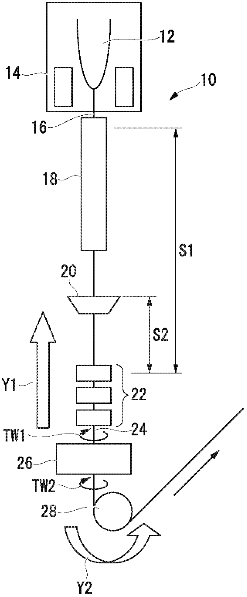
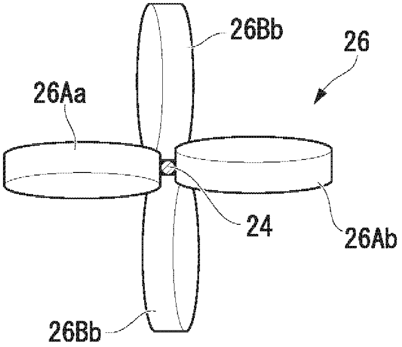
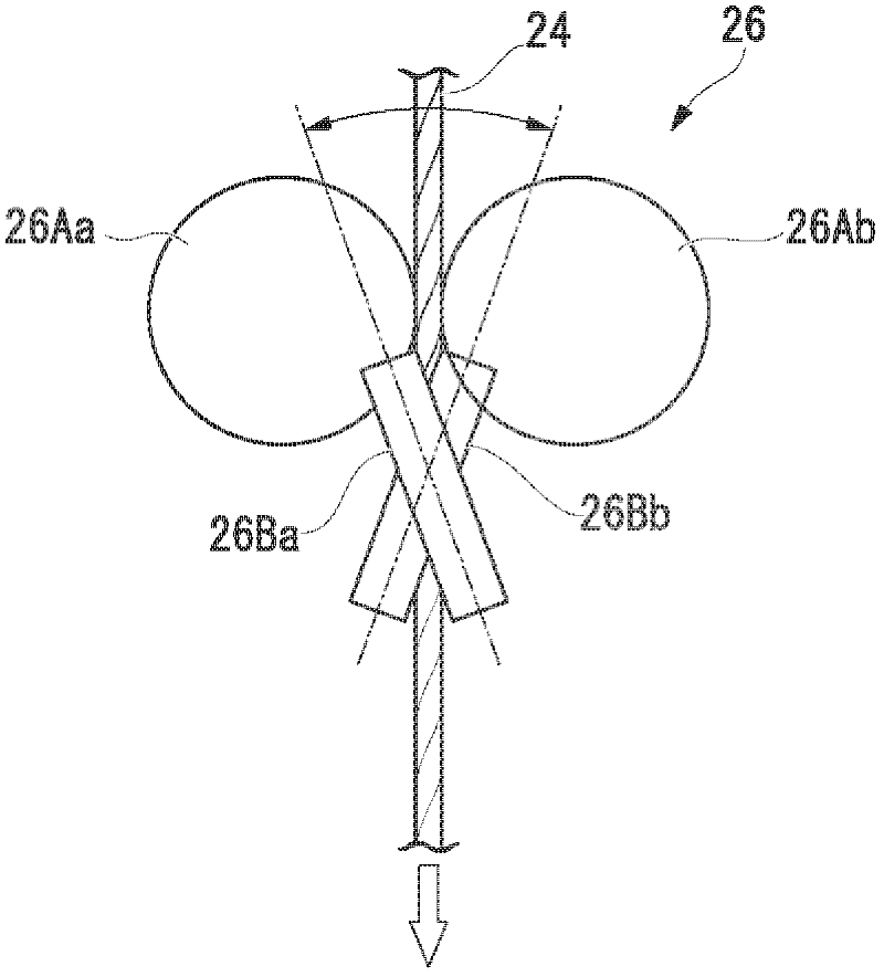
[0093] use figure 1 The fiber optic cable manufacturing device shown, and using image 3 The device shown is used as the twist imparting device in the manufacturing device, and the elastic twist imparted is manufactured on the basis of the silica glass-based optical fiber having a two-layer coating structure having the characteristics of a general single-mode optical fiber according to the above-mentioned method of the present invention. (twisted) fiber optic cable. The spinning speed (drawing speed) from the optical fiber preform was set to 2000 mm / min. In addition, the coating device employs a 2-layer simultaneous coating method (wet on wet method) in which two types of coating resins are coated at one position. UV curable urethane acrylate resin (Young's modulus when hardened is 0.5MPa) is used as the resin (first material) of the primary cover layer, UV curable urethane acrylate resin (Young's modulus when hardened is 0.5MPa) 1000MPa) as the resin (second material) of t...
Embodiment 2
[0106] use Figure 8 The fiber optic cable manufacturing device shown, and using image 3 The device shown is used as the twist imparting device 26 in the manufacturing apparatus. According to the above-mentioned method of the present invention, it is manufactured on the basis of a silica glass-based optical fiber with a double-layer coating structure having the characteristics of a general single-mode optical fiber. Twisted (twisted) fiber optic cable. The spinning speed (drawing speed) from the optical fiber preform was set to 1500 mm / min. In addition, as a cover-hardening method, such as Figure 8 As shown, different methods (wet on dry method) of coating and covering resin are applied to two positions respectively. UV curable urethane acrylate resin (Young's modulus when hardened is 1.0MPa) is used as the resin (first material) of the primary cover layer, UV curable urethane acrylate resin (Young's modulus when hardened is 500MPa) ) as a resin (second material) for the...
Embodiment 3
[0112] In the same manner as in Example 2, an optical fiber cable with an elastic twist (twist) and a two-layer coating structure was produced. In addition, as for the viscosity of the covering resin at the time of covering (liquid state), the viscosity of the first material was adjusted to 3 Pa·sec and the viscosity of the second material was adjusted to 0.1 Pa·sec in the same manner as in Example 2. The swing angle and the swing speed of the twist imparting device are set so that the twist imparted by the twist imparting device to the optical fiber, the curve in the length direction of the optical fiber is a trapezoidal wave in which the twist direction is periodically reversed, and the period T is 30m, the maximum twist angle MA of the cumulative twist angle is 120000°. The optical fiber that has passed through the twist imparting device is extracted by a take-out machine, and wound up by a winder via a dancer pulley to obtain an optical fiber with elastic twist (twist) app...
PUM
| Property | Measurement | Unit |
|---|---|---|
| viscosity index | aaaaa | aaaaa |
| viscosity index | aaaaa | aaaaa |
| viscosity index | aaaaa | aaaaa |
Abstract
Description
Claims
Application Information