Light Emitting Device

a technology of light-emitting devices and light-emitting tubes, which is applied in the direction of point-like light sources, vehicle headlamps, spectral modifiers, etc., can solve the problems of poor color reproducibility, difficult adjustment of control, and so as to achieve excellent color reproducibility, less variance in color tones, and wider divergence angle

Active Publication Date: 2008-04-17
NICHIA CORP
View PDF16 Cites 125 Cited by
  • Summary
  • Abstract
  • Description
  • Claims
  • Application Information

AI Technical Summary

Benefits of technology

[0201] A translucent member composed of a covering member (wavelength conversion member) containing a fluorescent substance or the like was described above, but in the following case, it is possible to use a translucent member composed of a covering member or the like, without a fluorescent substance necessarily being required. That is, when the light guide distal end member is formed form a material that reflects the light from the light source, or when the light guide is such that the diameter of the center part (core) of its cross section is formed larger only at the end on the translucent member side, or when a light reflecting film is provided to the portion of the translucent member into which light is guided, or when an scatter preventing member is formed between the translucent member and the light guide and / or on the surface of the translucent member except for the portion from which wavelength-converted light is guided to the outside, or when a plurality of light guides are provided, or when the translucent member, along with the end of the light guide, covers all or part of the end of the light guide distal end member, the effect obtained will be basically the same as when using the wavelength conversion member discussed in the effect of the invention. In this Specification, a case of using a wavelength conversion member in which a fluorescent substance or the like was contained in a covering member as the translucent member was described in order to simplify description, but in these cases it is possible to replace the wavelength conversion member with a translucent member that does not contain a fluorescent substance or the like. When a translucent member that does not contain a fluorescent substance is used, the light source may be one that excites a fluorescent substance, that is, just an ordinary light source rather than an excitation light source. Therefore, in the various cases mentioned above, the excitation light source may be replaced with a light source that does not excite.
[0202] There are no particular restrictions on the translucent member as long as it is a material capable of transmitting light from the light source, but examples include the above-mentioned covering member alone, and this covering material containing the above-mentioned filler or the like. This allows the light obtained from the light source to be used directly, without first undergoing wavelength conversion, and allows the directivity of the light to be controlled. Also, adding a filler allows the light to be scattered before being taken out. Light Guide Distal End Member
[0203] The end of the light guide, or in other words the end which is not connected to the excitation light source is preferably supported by a light guide distal end member. The radiating light from the light guide can easily be fixed by this light guide distal end member. Furthermore, depending on the material and shape thereof, the light emitting efficiency can be increased and the assembly of the light emitting device can be simplified. Therefore, the light guide distal end member may be constructed using any material and configuration so long as the light guide can be supported. As shown by Q in FIG. 4j, when a step is formed on the light guide side of the light guide distal end member, this step serves as a contact face that facilitates the fixing of a lighting device, for instance.
[0204] The light guide distal end member is preferably formed from a material which has high reflectivity towards the wavelength converted light and / or the excitation light, high refractive index for light, or high thermal conductivity, or a material which provides two or more of these characteristics. For instance, a material where reflectivity is 80% or higher at the peak wavelength of the wavelength converted light and / or the excitation light, the refractive index is n: 1.4 or higher for light in the 350 to 500 nm range, and / or the thermal conductivity is 0.1 W / m° C. or higher is preferable. Specific examples include Ag, Al, ZrO2, borosilicate glass, stainless steel (SUS), carbon, copper, and barium sulfate or the like. Of these materials, if ZrO2 is used the reflectivity will be high and machining for the light guide to pass through will be simple, but if stainless steel is used, the tensile strength can easily be maintained, and therefore forming with ZrO2 or stainless steel (for instance SUS303 or the like) is preferable.
[0205] Furthermore, only the end surface of the light guide distal end member (the surface which is conform with end surface of the light guide, see M in FIG. 3a for instance) preferably has a mirror for specular reflection or diffuse reflection, or may have a concave and convex shape for. Thereby if excitation light which has once been radiated from the light guide and / or light which has had the wavelength converted returns to the light guide side, the excitation light and the wavelength converted light can effectively be removed again by reflecting using the light guide distal end member, and therefore the optic output can be increased. Furthermore, if the end surface has a concave and convex shape, the adhesion of the wavelength conversion member to the light guide distal end member can be increased, thermal dissipation of the wavelength conversion member can be increased, and peeling or degradation of the wavelength conversion member can be prevented. Incidentally, a surface which has specular reflectivity and / or a concave and convex shape preferably is used not only for the light guide distal end member, but also for the light guide end surface.
[0206] The light guide distal end member may for instance have a cylindrical shape in order to cover the outer circumference of the light guide, and various functional films / members which provide various functions to the end surface of the light guide may be integrated with or attached separately thereto, or a cover or cap or the like which covers the end surface of the light guide as well as other functional films / members or the like may be integrated with or separately attached thereto. Incidentally, if the light guide distal end member has a cylindrical configuration, the diameter is for instance preferably 3 mm or less.

Problems solved by technology

Nevertheless, a semiconductor laser has a narrower half band width than a light emitting diode, so a problem with a conventional endoscope device in which the white light source 111 comprised the red semiconductor laser 111a, the green semiconductor laser 111b, and the blue semiconductor laser 111c was that differences in the intensity of the various semiconductor lasers resulted in variance in the color tones, and this led to poor color reproducibility.
Also, because at least three kinds of semiconductor laser were required with a conventional endoscope device, the output of each semiconductor laser had to be controlled to obtain a specific white light, and adjusting this control proved difficult.
Furthermore, a semiconductor laser has a narrower angle of visibility than a light emitting diode, and its emission intensity is extremely high in the front direction, so a another problem is that even with white light, the color tone can vary due to slight misalignment of the various semiconductor lasers.

Method used


Image

  • Light Emitting Device
  • Light Emitting Device
  • Light Emitting Device

Examples


example 1

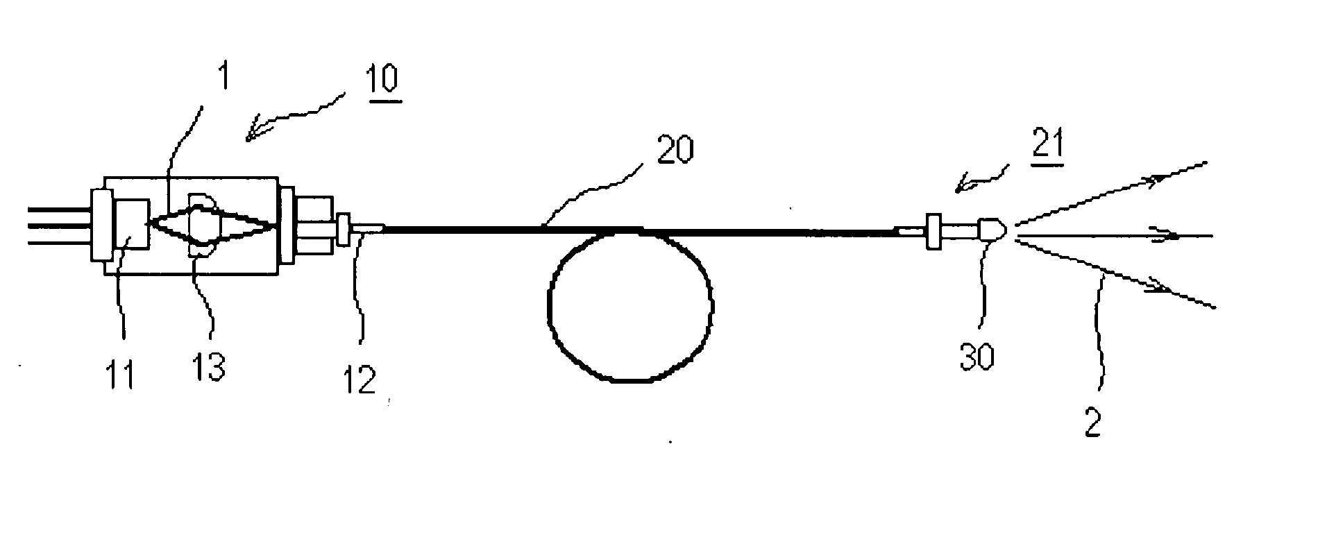
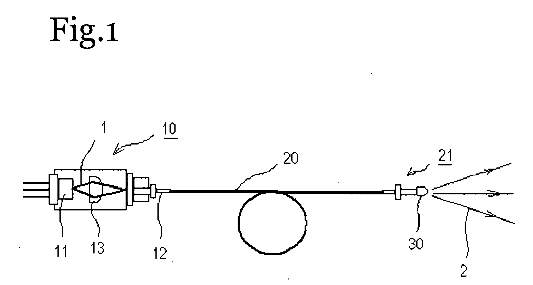
[0228] As shown in FIG. 1, this light emitting device comprised an excitation light source 10, a light guide 20, and a wavelength conversion member 30.

[0229] A light emitting element 11 which is a laser diode composed of a GaN-based semiconductor having an emission peak wavelength near 405 nm was used as the excitation light source 10. A lens 13 for converging excitation light 1 from the laser diode was disposed on the front face of this laser diode.

[0230] The light guide 20 was connected at one end to the emission portion 12 of the excitation light source 10, and connected at the other end to the output portion 21. The light guide 20 used here was an SI-type, made of quartz, with a core diameter of 114 μm and a cladding diameter of 125 μm.

[0231] The wavelength conversion member 30 was molded such that the fluorescent substance would be uniformly dispersed in the resin, and was attached to the output portion 21.

[0232] The fluorescent substance was a combination of Ca10(PO4)6Cl2:...

example 2

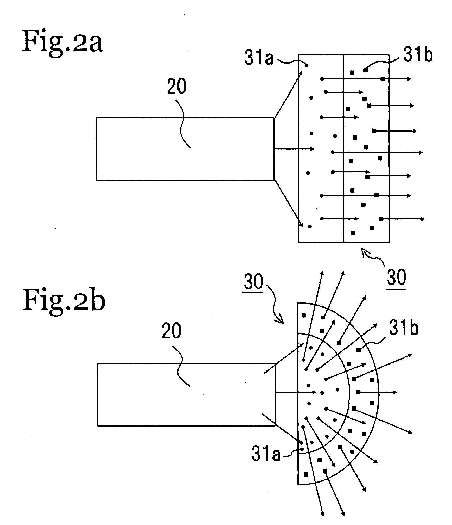
[0236] With this light emitting device, two types of fluorescent substance were used, CCA and YAG. Each fluorescent substance was uniformly mixed with a resin. The wavelength conversion member that was used had a three-layer structure in which YAG, CCA, and YAG were laminated in that order, starting from the side closest to the excitation light. The distal end of the light guide was supported by a light guide distal end member, and the wavelength conversion member was disposed so as to integrally cover both the light guide and the light guide distal end member, but other than the above, the structure was the same as that of the light emitting device in Example 1.

[0237] Each fluorescent substance and the resin were mixed in a ratio of 2:1, and the thickness of each layer was about 100 μm.

[0238] Using this structure allowed the desired white light to be obtained, and a light emitting device with high emission efficiency was obtained by combining with a light emitting element having ...

example 3

[0242] As shown in FIG. 1, this light emitting device comprised a excitation light source 10, a light guide 20, and a wavelength conversion member 30. The excitation light source 10 and the light guide 20 were the same as in Example 1. The wavelength conversion member 30 comprised a fluorescent substance 31 of BaMg2Al16O27:Eu,Mn in silicone resin, mixed in a weight ratio of 1:1, kneaded until uniform, and molded.

[0243] With a light emitting device with this structure, the excitation light 1 emitted from the laser diode was transmitted through the lens 13 and converged at the emission portion 12. The converged excitation light 1 was transmitted through the light guide 20 to the output portion 21. The excitation light 1 guided out of the output portion 21 was directed at the fluorescent substance of the wavelength conversion member 30 and its wavelength was converted, so that light 2 having the emission spectrum shown in FIG. 7 was obtained.

[0244] This light was emitted as green lig...


PUM


Abstract

A light emitting device, comprises: an excitation light source that emits excitation light; a wavelength conversion member that absorbs the excitation light emitted from the excitation light source, converts its wavelength, and releases light of a predetermined wavelength band; a light guide in which the center part (core) of its cross section has a refractive index that is higher than the refractive index of the peripheral portion (cladding), and which guides the light emitted from the wavelength conversion member to the outside; and wherein the wavelength conversion member is produced by laminating a plurality of layers that wavelength-convert different wavelengths of light.

Description

TECHNICAL FIELD [0001] The present invention relates to a light emitting device mainly having an excitation light source, a wavelength conversion member, and a light guide. BACKGROUND ART [0002] Conventionally, endoscope devices for in vivo observations and for performing treatment during observations, and fiber scopes for observing in extremely narrow or dark spaces have been widely used. [0003] Endoscopes and fiber scopes are constructed with extremely minute light guides and are able to illuminate spaces or the like such as inside body cavities like the stomach or other gaps or the like because the fibers transfer light which has been radiated from a light source. [0004] In order to efficiently illuminate using minute fibers, the light source is required high brightness. Furthermore, when observing and in some cases diagnosing an affected area of an organ or within cavities, accurate reproduction of color information is important. Thus, the light source for endoscopes and fiber s...

Claims


Application Information

Patent Timeline
Patent Type & Authority Applications(United States)
IPC IPC(8): A61B1/07A61B1/00A61B1/06F21V8/00F21Y101/02G02B6/00G02B6/42H01L33/00H01L33/32H01L33/50H01L33/58
CPCA61B1/0653A61B1/07A61B18/22A61B2018/2255A61B1/0017G02B6/0008G02B6/4206G02B6/4249G02B6/4298G02B6/0003F21K9/64F21Y2115/30F21S41/16F21V9/38H01L33/504H01L33/505H01L33/507H01S5/02212H01S5/0087H01S5/02251A61B2018/2266A61B2018/2272
Inventor HAMA, ATSUTOMOHONDA, TOMOTAKANAGAHAMA, SHINICHITAKEICHI, JUNJIMURAZAKI, YOSHINORITAMAKI, HIROTOHAYASHI, YUKIHIRO
Owner NICHIA CORP
Why Eureka
Try Eureka