Method and system for real-time prognosis analysis and usage based residual life assessment of turbine engine components and display

a technology of turbine engine and prognosis analysis, applied in the field of real-time prognosis analysis and usage based residual life assessment of turbine engine components and display, can solve the problems of reducing the power output of a given fuel burn, surface damage of turbine parts, and loss of aerodynamic and thermal efficiency, so as to facilitate proactive repair and overhaul decisions, the effect of reducing the cost of ownership of the engin

Active Publication Date: 2011-06-09
KOUL ASHOK
View PDF14 Cites 116 Cited by
  • Summary
  • Abstract
  • Description
  • Claims
  • Application Information

AI Technical Summary

Benefits of technology

[0027]The object of the invention is to provide a physics based prognostics system for continuously evaluating the usage and operating environment based gas path as well as component temperature profiles, thermal-mechanical loads and material damage accumulation in multiple engine components to accurately predict their life consumption and residual life as a function of usage to facilitate proactive repair and overhaul decisions, predict individualized and cost effective TBO for the engine, with the ultimate goal of reducing the cost of ownership of the engine.

Problems solved by technology

Surface damage occurs in turbine parts as a result of erosion, corrosion, fretting, wear or impact by foreign objects and particulates.
This loss of surface integrity and component geometry leads to losses in aerodynamic and thermal efficiency, and reduced power output for a given fuel burn.
More importantly, parts suffer internal structural damage, which leads to metallurgical deterioration and ultimately component failure, engine shutdown and unscheduled maintenance.
The cyclic nature of power demands and the high frequency pressure fluctuations due to turbulence in gas flows leads to internal microstructural damage in the form of fatigue, cold creep, stress corrosion, low cycle fatigue (LCF), high cycle fatigue (HCF) and corrosion fatigue in rotating as well as stationary parts such as compressor blades, vanes and discs, turbine discs, shafts and spacers.
The components in the hot gas stream, such as turbine discs and blades, guide vanes, seals, and combustor casings and linings, suffer from cyclic fluctuations in temperature as well as inertia loads, both of which also cause internal microstructural damage due to high temperature creep, thermal fatigue, thermal-mechanical fatigue (TMF), creep-fatigue environment interactions and / or high temperature low cycle fatigue (HTLCF), and various combinations of these mechanisms.
The net result of the combined action of all of these damage modes is that many of these high cost components have finite lives.
The challenge to manufacturers and the operators of engines is to determine when to inspect and overhaul the engine, and when to repair or replace the used parts, all of which involve downtime of equipment and high cost for manpower and replacement parts.
Failure to deal adequately with any of these challenges may lead to unexpected failures, unscheduled shutdown and a cascade of damage to otherwise sound components.
Major overhaul is by far the most expensive maintenance action item during the life cycle management of turbine engines.
Component level internal microstructural damage and distortion due to creep, LCF or TMF, is difficult to detect, and only empirical models are available to guess damage accumulation rates and the critical levels of damage beyond which remedial action would be essential.
This life can be harnessed using inspection based life cycle management of parts but the inspection intervals under creep, fatigue and combined loading conditions can only be developed using material physics based crack propagation modeling techniques.
However, the life consumption and residual life of different components in EPLTS based systems are still computed using pre-determined safe life limits as opposed to actual usage based predicted life.
Diagnostics based prognostics techniques, however, are only capable of picking gross faults and can be useful in preventing catastrophic failures but cannot be effectively used for residual life assessment purposes.
At present, there is no real-time prognostics system that has been developed for the predictive maintenance of multiple turbine engine components using physics based gas path modeling and loads and damage analysis techniques.
These systems typically use sensors and numerous advances have been made in monitoring systems to provide alarms and improve displays However, apart from predicting compressor fouling, the inability of performance monitoring systems to assist with predictive maintenance and TBO prediction remains unchanged.
Extensive basic scientific research has indicated that component level failure is caused by usage-based loads that are responsible for the development of damage at the microstructural level.
While identification of thermal boundary conditions is important for gauging the component level structural response, the effect of underlying deformation and fracture mechanisms on life consumption and residual life has not received equal attention.
The use of empirical life prediction techniques also requires the generation of large but very expensive material databases along with a lot of field experience to accurately predict the future component behavior.
Thus, initial and dynamic variability of microstructures in individual sets of components along with changes in in-service usage and operational conditions lead to variability in gas path temperatures and thermal-mechanical loads that control the life consumption and residual life.
To date, there has been no attempt made to provide the engine users with the variability analysis of life consumption or residual life of multiple engine components on the basis of actual usage and usage based thermal-mechanical loads and material physics based damage analysis, nor provide the capability for continuous real-time variability analysis and display.

Method used


Image

  • Method and system for real-time prognosis analysis and usage based residual life assessment of turbine engine components and display
  • Method and system for real-time prognosis analysis and usage based residual life assessment of turbine engine components and display
  • Method and system for real-time prognosis analysis and usage based residual life assessment of turbine engine components and display

Examples


Embodiment Construction

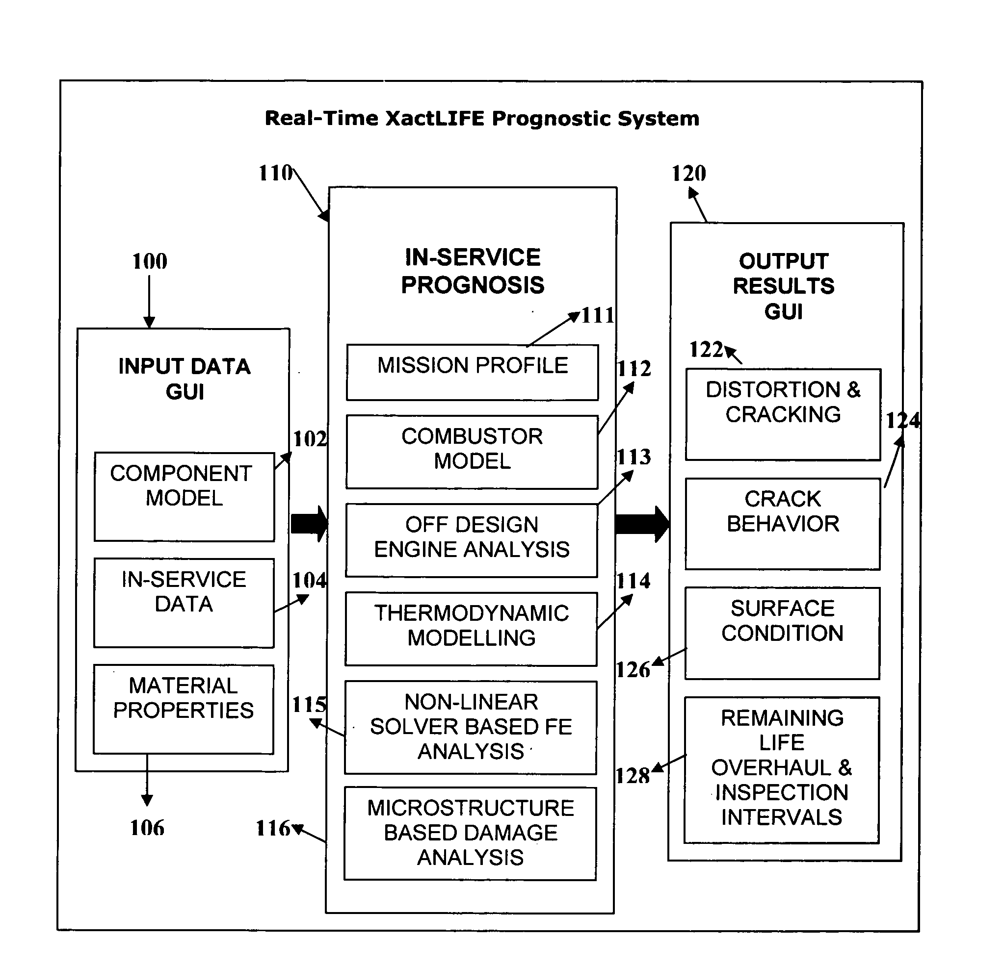
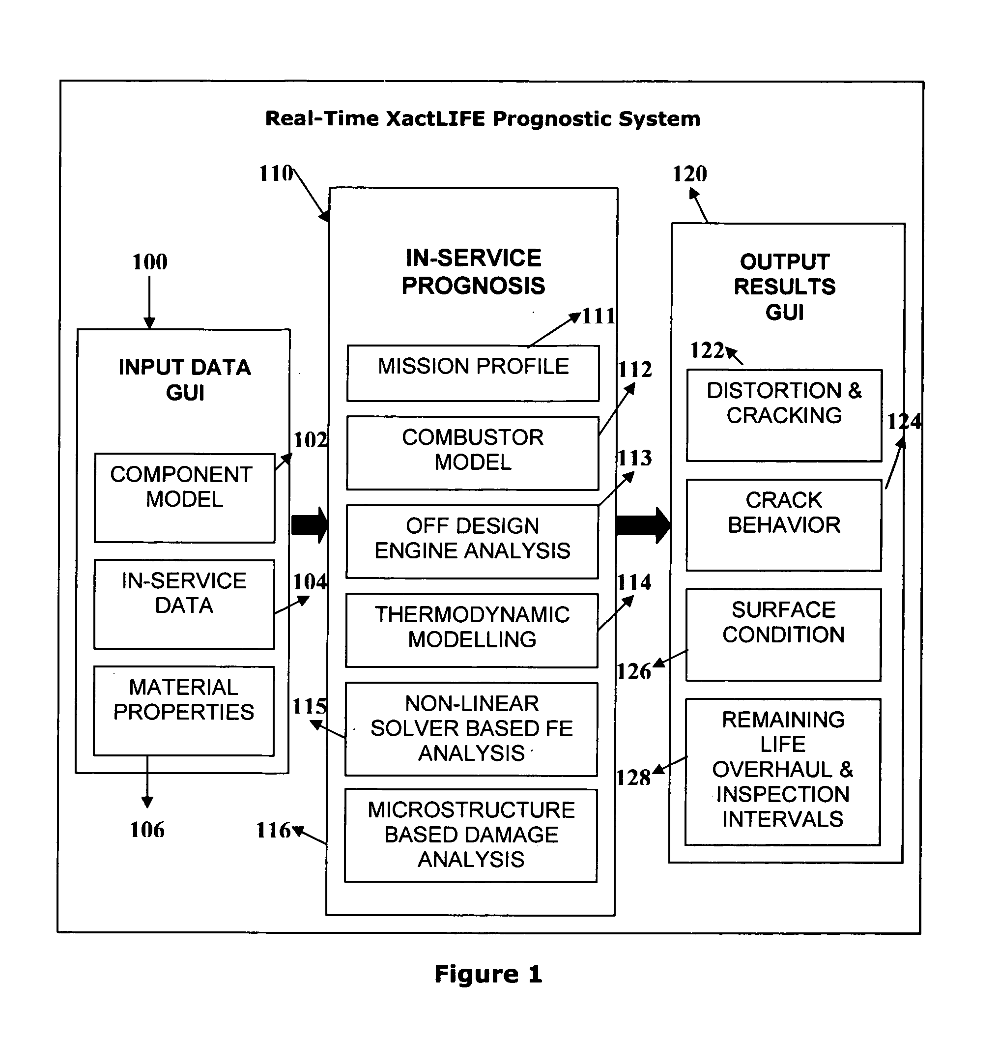
[0072]FIG. 1 illustrates a computer-based prognostics system consisting of three main parts: input interface 100, prognostics processor 110 and output interface 120 which are synchronized through a software architecture. In the part 100, the input interface has a finite element component model 102, in-service operating data 104 (temperature, pressure, rpm, etc.), from pre-existing sensors and signal processing modules installed in the machinery under investigation; and material properties data 106. The prognostics processor 110 consists of a mission profile analyzer module 111, a combustor modeling module 112, off-design engine analysis module 113, thermodynamic modeling module 114, non-linear finite element analysis module 115, and a microstructure-based damage analysis module 116. The flow of information between these modules is explained in more detail in FIG. 17.

[0073]The output interface 120 consists of distortion and cracking data 122, crack behaviour data 144, surface conditi...


PUM


Abstract

A method and system for performing continuous (real-time) physics based prognostics analysis as a function of actual engine usage and changing operating environment. A rule-based mission profile analysis is conducted to determine the mission variability which yields variability in the type of thermal-mechanical loads that an engine is subjected to during use. This is followed by combustor modeling to predict combustion liner temperatures and combustion nozzle plane temperature distributions as a function of engine usage which is followed by off-design engine modeling to determine the pitch-line temperatures in hot gas path components and thermodynamic modeling to compute the component temperature profiles of the components for different stages of the turbine. This is automatically followed by finite element(FE) based non-linear stress-strain analysis using an real-time FE solver and physics based damage accumulation, life consumption and residual life prediction analyses using microstructural modeling based damage and fracture analysis techniques.

Description

TECHNICAL FIELD[0001]The present invention relates to real-time monitoring of turbine engines under off-design engine operating conditions and performing physics based prognostics analysis of multiple engine components for life consumption and residual life prediction before the development of actual material damage and discernable faults in the said components in real time. More specifically, the invention relates to a system and methods for real time monitoring and performing modified rain-flow and rule based mission profile analysis for assessing variability in damage accumulation modes and mechanisms and fracture mechanisms that are operative as a function of real time engine usage, running physics based combustor modeling for obtaining combustor liner and combustor nozzle temperature profiles, performing thermodynamic analysis for obtaining gas path temperature profiles, performing heat transfer analysis for obtaining component temperature profiles, performing material physics ...

Claims


Application Information

Patent Timeline
Patent Type & Authority Applications(United States)
IPC IPC(8): G06F19/00
CPCG05B23/0283G05B23/0245
Inventor KOUL, ASHOK
Owner KOUL ASHOK
Why Eureka
Try Eureka