Composite material cutting machine

A composite material and material cutting machine technology, which is applied to the attachment of shearing machines, shearing machine equipment, shearing devices, etc., can solve the problems of broken and broken materials and cannot be completely cut at one time, and achieve the effect of eliminating broken and broken wires

Pending Publication Date: 2020-07-10
SUZHOU MORE V COMPOSITE MATERIAL
View PDF0 Cites 0 Cited by
  • Summary
  • Abstract
  • Description
  • Claims
  • Application Information

AI Technical Summary

Problems solved by technology

[0002] The material cutting machine generally includes a material guide frame, front and rear feeding groups and a material cutting mechanism. The front feeding group and the rear feeding group usually convey materials at the same speed.

Method used


Image

  • Composite material cutting machine
  • Composite material cutting machine
  • Composite material cutting machine

Examples


Embodiment Construction

[0021] The present invention will be further described below in conjunction with the embodiments shown in the accompanying drawings.

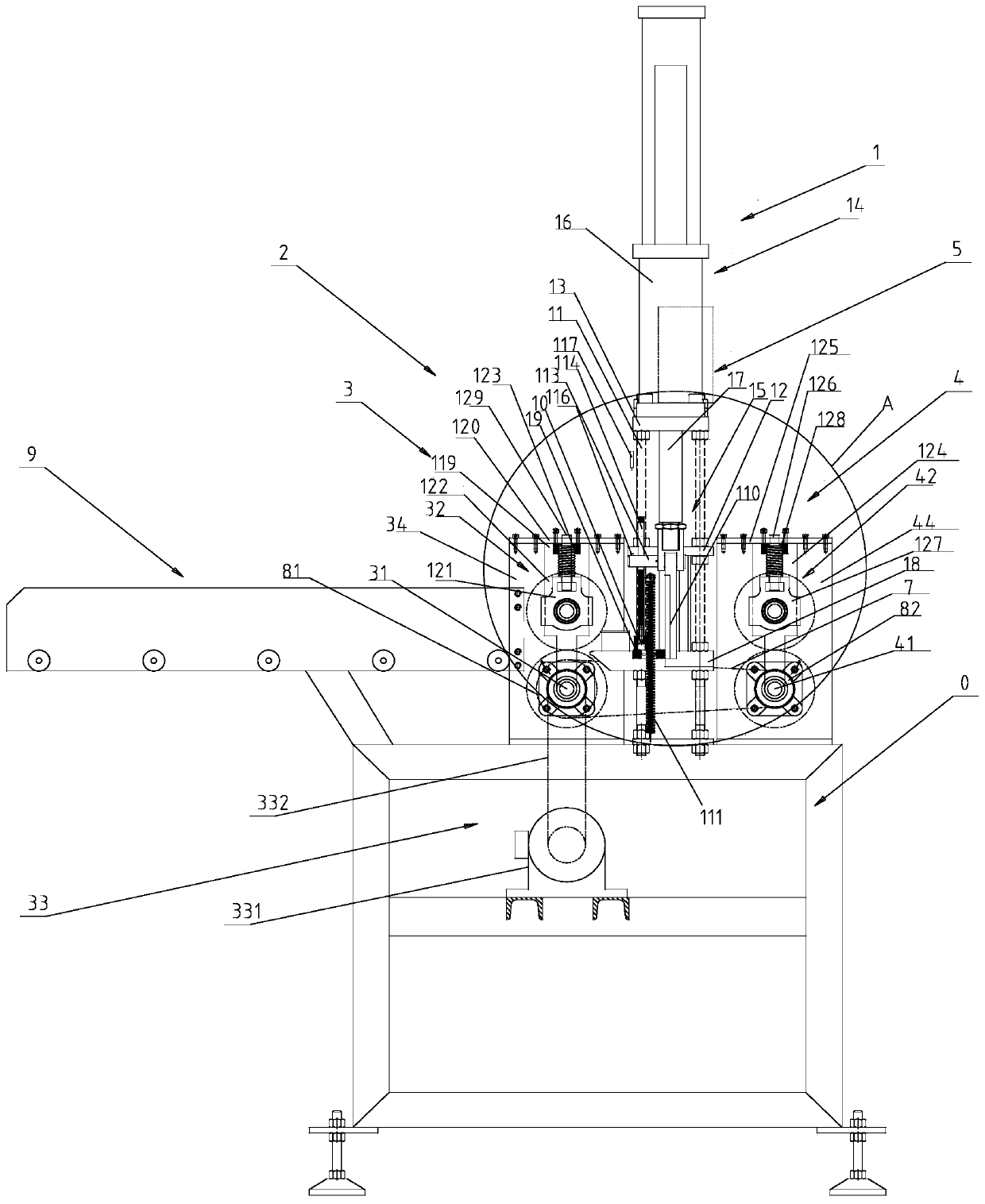
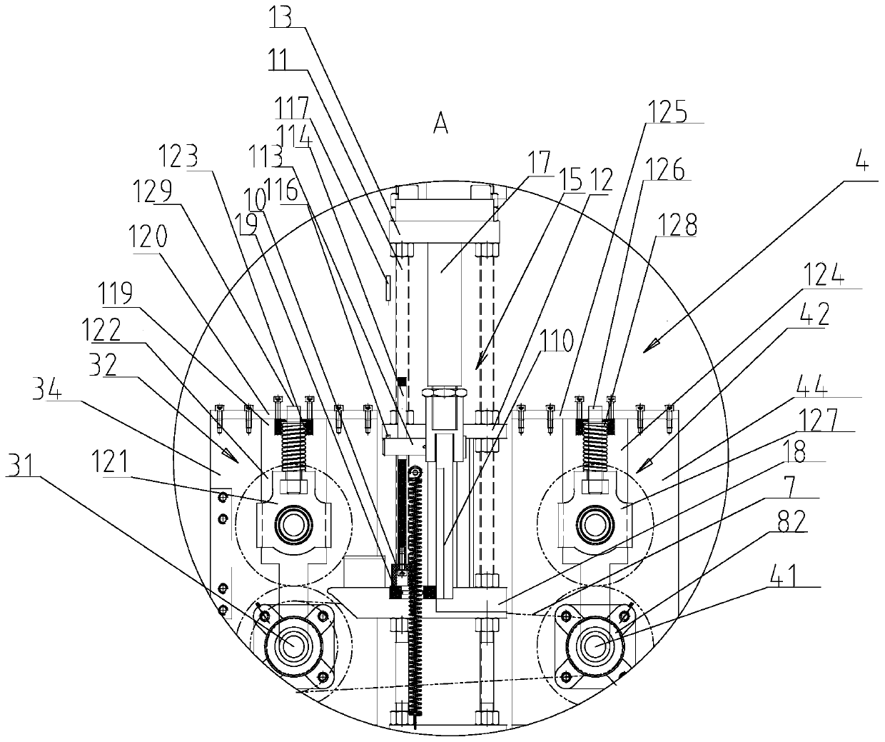
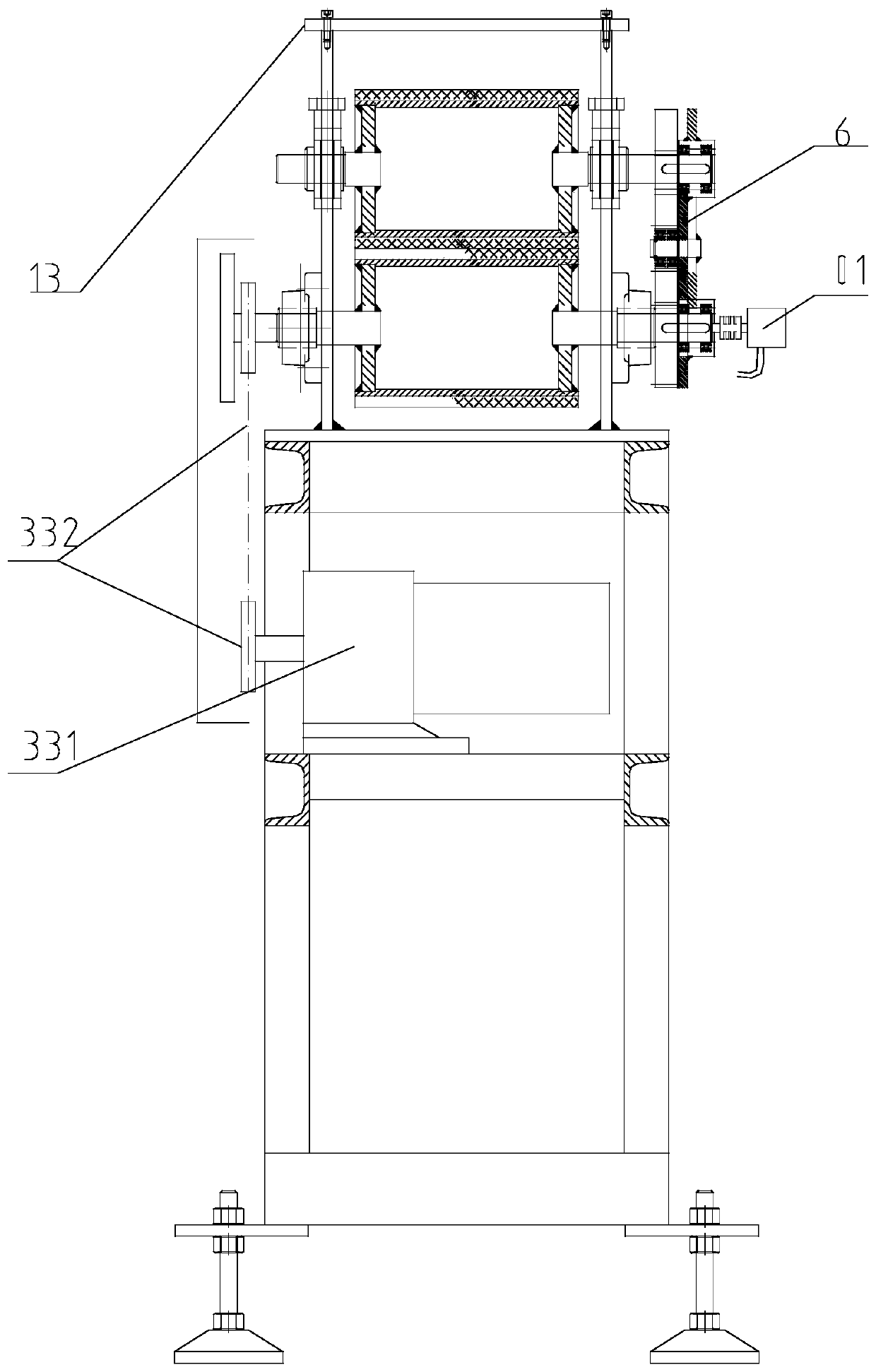
[0022] Such as Figure 1-5 As shown, the composite material cutting machine includes an underframe 0, a material guide frame 9, a feeding mechanism 2, and a cutting mechanism 1. The feeding mechanism 2 includes a front feeding group 3 located upstream of the cutting mechanism 1, and a Rear feeding group 4 and control cabinet 5;

[0023] The front feeding group 3 includes a front lower power roller 31, a front upper floating roller 32, a feeding drive member 33 and two oppositely arranged front vertical plates 34, and the front upper floating roller 32 can slide up and down and is rotatably arranged between the front vertical plates 34 , the front lower power roller 31 is rotatably located between the front vertical plates 34, the feeding drive member 33 is in transmission connection with the front lower power roller 31, and the rear feeding gr...


PUM


Abstract

The invention discloses a composite material cutting machine. The composite material cutting machine comprises an underframe, a material guide frame, a feeding mechanism and a material cutting mechanism. The feeding mechanism comprises a front feeding set located upstream relative to the material cutting mechanism, and a rear feeding set located downstream relative to the material cutting mechanism. The material conveying speed of the rear feeding set is greater than that of the front feeding set. According to the composite material cutting machine, a material cutting structure is utilized tocomplete basic cutting of materials; and after the cutting is completed, because the feeding speed of the front feeding set is lower than that of the rear feeding set, broken materials and unbroken materials drag each other to achieve complete material breaking, thereby eliminating the problem that the materials are not completely broken.

Description

technical field [0001] The invention belongs to the field of composite material production equipment, in particular to a composite material cutting machine. Background technique [0002] The material cutting machine generally includes a material guide frame, a front and rear feeding group and a material cutting mechanism. The front feeding group and the rear feeding group usually convey materials at the same speed. Contents of the invention [0003] The purpose of the present invention is to provide a composite material cutting machine that can cut materials of different thicknesses without the problem of chains and broken wires after cutting. [0004] In order to achieve the above object, the technical solution adopted by the present invention is: a composite material cutting machine, which includes an underframe, a material guide frame, a feeding mechanism and a cutting mechanism, and the feeding mechanism includes a The front feeding group, and the rear feeding group...

Claims


Application Information

Patent Timeline
IPC IPC(8): B23D31/00B23D33/02
CPCB23D31/002B23D33/02
Inventor 艾清平张栋
Owner SUZHOU MORE V COMPOSITE MATERIAL
Why Eureka
Try Eureka